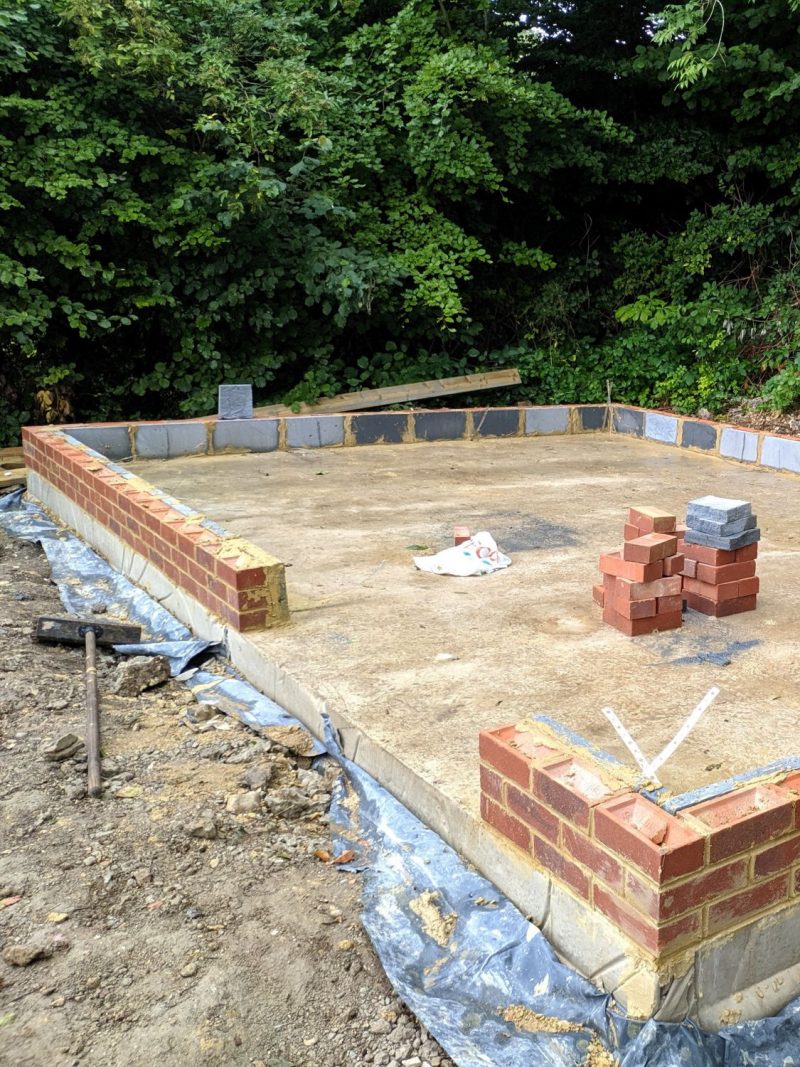

Once the brick plinth had been raised I was ready to start making the timber frames. This design uses frames that are constructed prior to placement and then nailed together at the corners. Before I started I bought a Paslode IM350 nail gun which was by far the most used tool in this project and definitely a worthwhile investment.
For the walls I used treated 4×2″ studs at 24″ centres; usually this would require noggins to stiffen the wall but as the building did not require building regulations I decided against using them. I had to sheathe the walls vertically for this reason.
Preparation
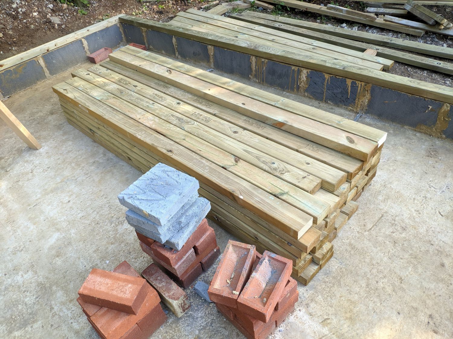
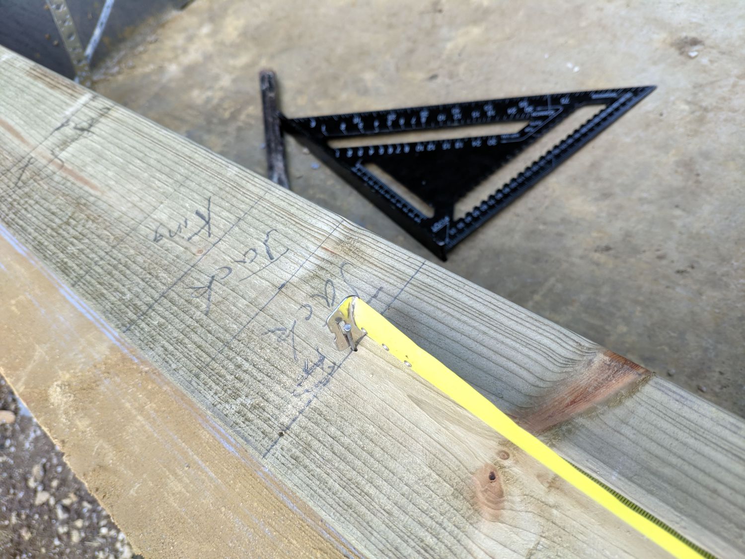
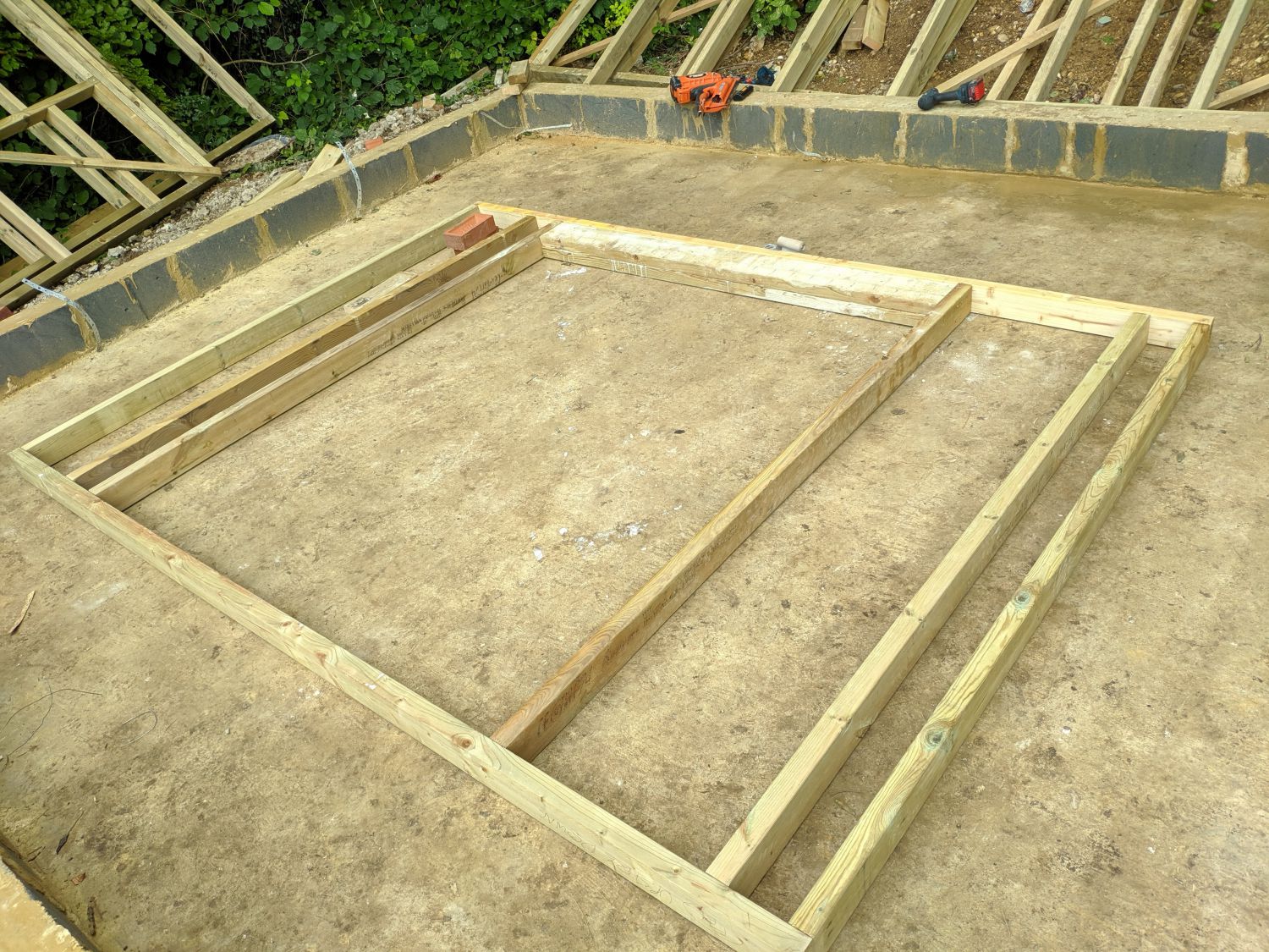
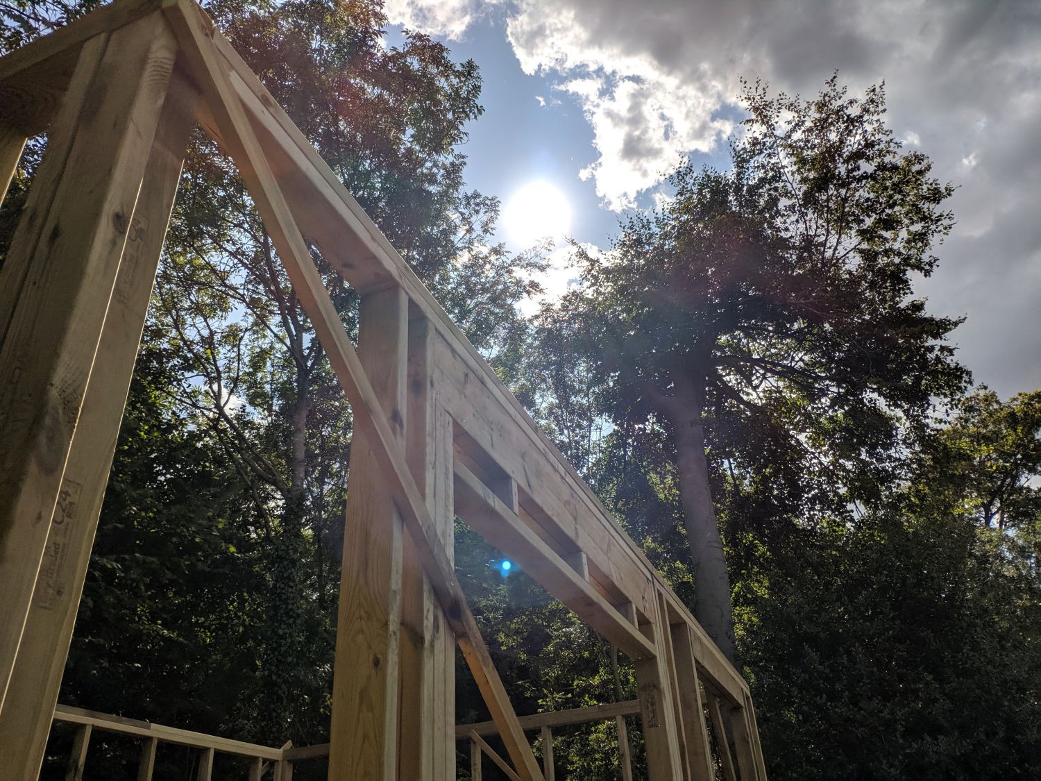
Before starting framing I cut the sole-plates to length and marked out the stud spacing including extra studs required for openings (two windows and a door). The studs were all 2090mm long which meant high 2.5m eaves (the max for permitted development); this was important as it meant I could fully utilise the ‘loft’ space without having to used raised ceiling ties for a higher internal roof. When marking out I had to offset the spacing at each corner to allow for the unconventional internal sheathing – I used three stud ‘California corners’ to allow for easier insulation. On the longer walls I used two wall segments to allow for easier lifting of the frames onto the dwarf wall.
Wall Framing
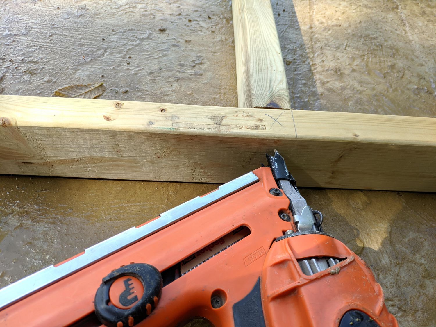
To frame the walls I first transferred the sole plate marking onto the top plate and then nailed together the exterior of the frame. For most of the framing, roof and walls, I used 3.1mm*90mm galvanised nails. Once I had confirmed the frame was fairly square (by measuring diagonals) I continued to nail in the rest of the studs, using the concrete slab as a flat working platform.
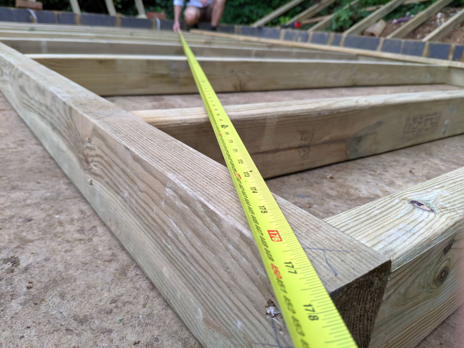
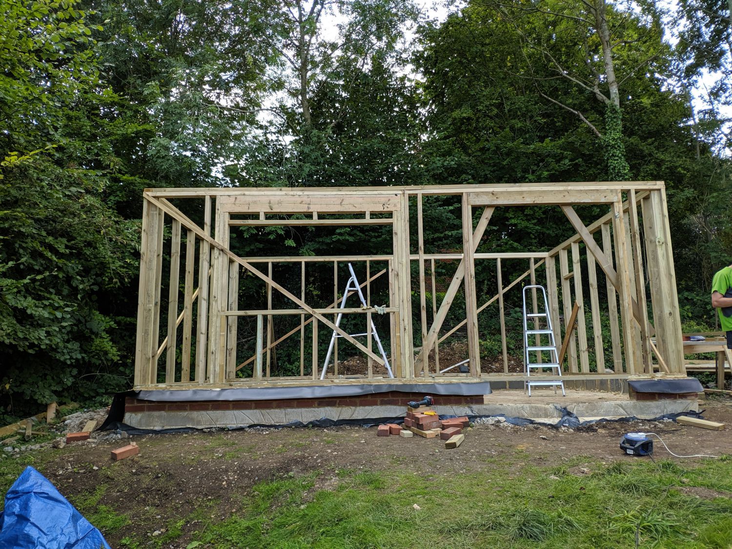
I ensured all the timbers were crowned in the same direction so the final wall wouldn’t be wavy. Finally I checked the diagonals to confirm they were the same, and braced the walls with temporary diagonal timbers. The back and left walls had no openings so I framed them first, laying them to the side to stand up later.
Window and door framing
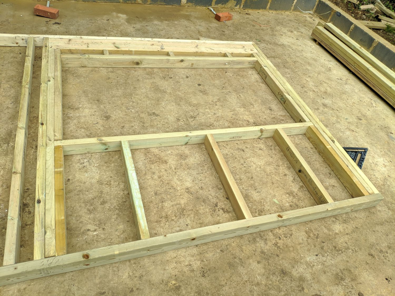

Once the simple walls had been framed I moved on to the front wall. This wall was more complex as it had a wide door opening and an even wider window opening. When framing openings, a lintel (2) is required to distribute the load from above down the trimmer (or jack) studs which are directly below the lintel. The king studs are regular length studs which sit directly to the side of the opening and provide further support to the opening. Finally, cripple studs (1,2) are placed above and below the opening at standard centres; at the top they transfer the roof load to the header and at the bottom they support the sill (4).
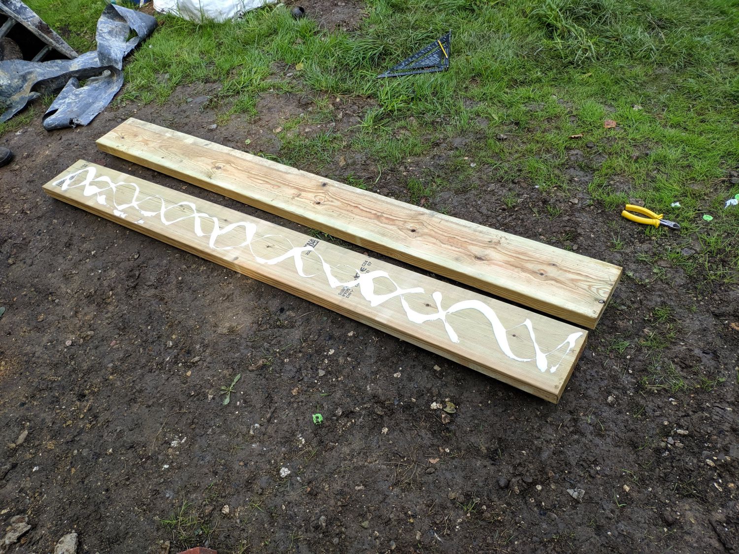
To make the lintel for the larger opening I laminated two 8×2 beams with wood glue; this opening is almost 2m so while this is probably overbuilt for a single storey building I wanted to be safe. I then nailed the beam with a ‘zig-zag’ nailing pattern, nailing every few inches on both sides.
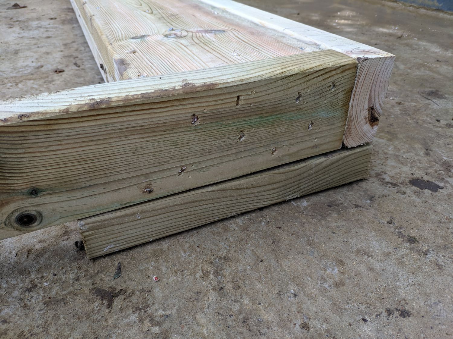
For the smaller opening I did the same but used 6x2s instead to reduce weight. I then nailed the lintels into place through the king studs using eight 90mm nails on each side for the larger one and six for the smaller one. All nailing schedules were obtained from US housing codes and should definitely be sufficient for this structure.
I put both headers right up against the top-plate so that if I ever need to make the openings taller (e.g. if I add an insulated floor over the concrete) it will be fairly straightforward. I used two trimmer studs for the large window opening.
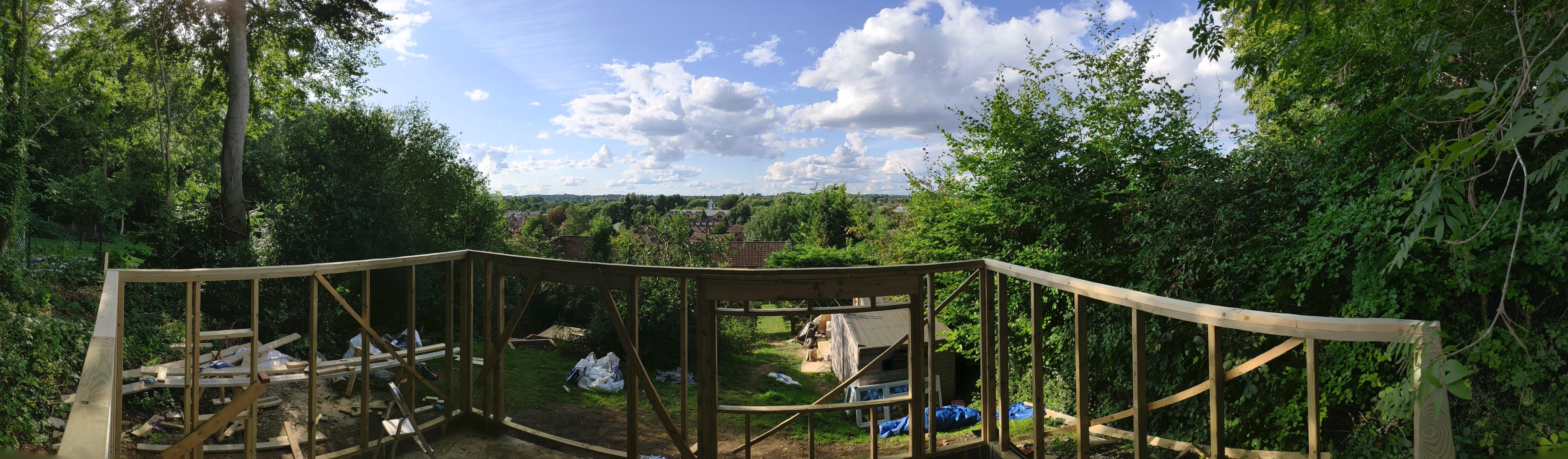
Assembling the walls
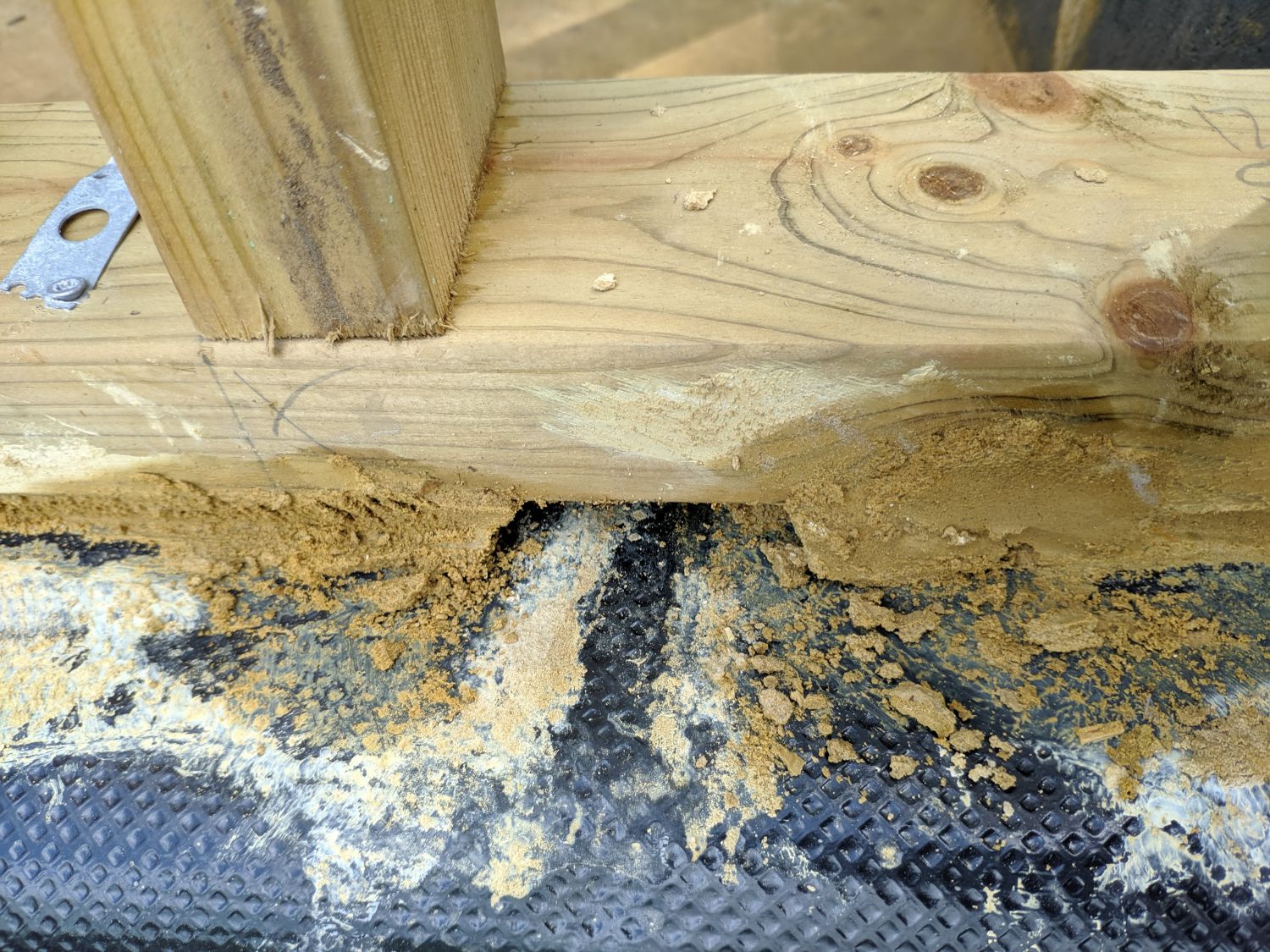
Once all the walls were assembled and laid out I started to prepare for the walls to be placed on the foundations. I rolled out 337.5mm damp proof course in line with the inner edge of the dwarf wall; the excess left flying outward was used later to create a drip edge allowing water running down behind the cladding to run out over the wall. Then, I cut some wedges from excess 8×2; these were adjusted to change the height and level of the wall.
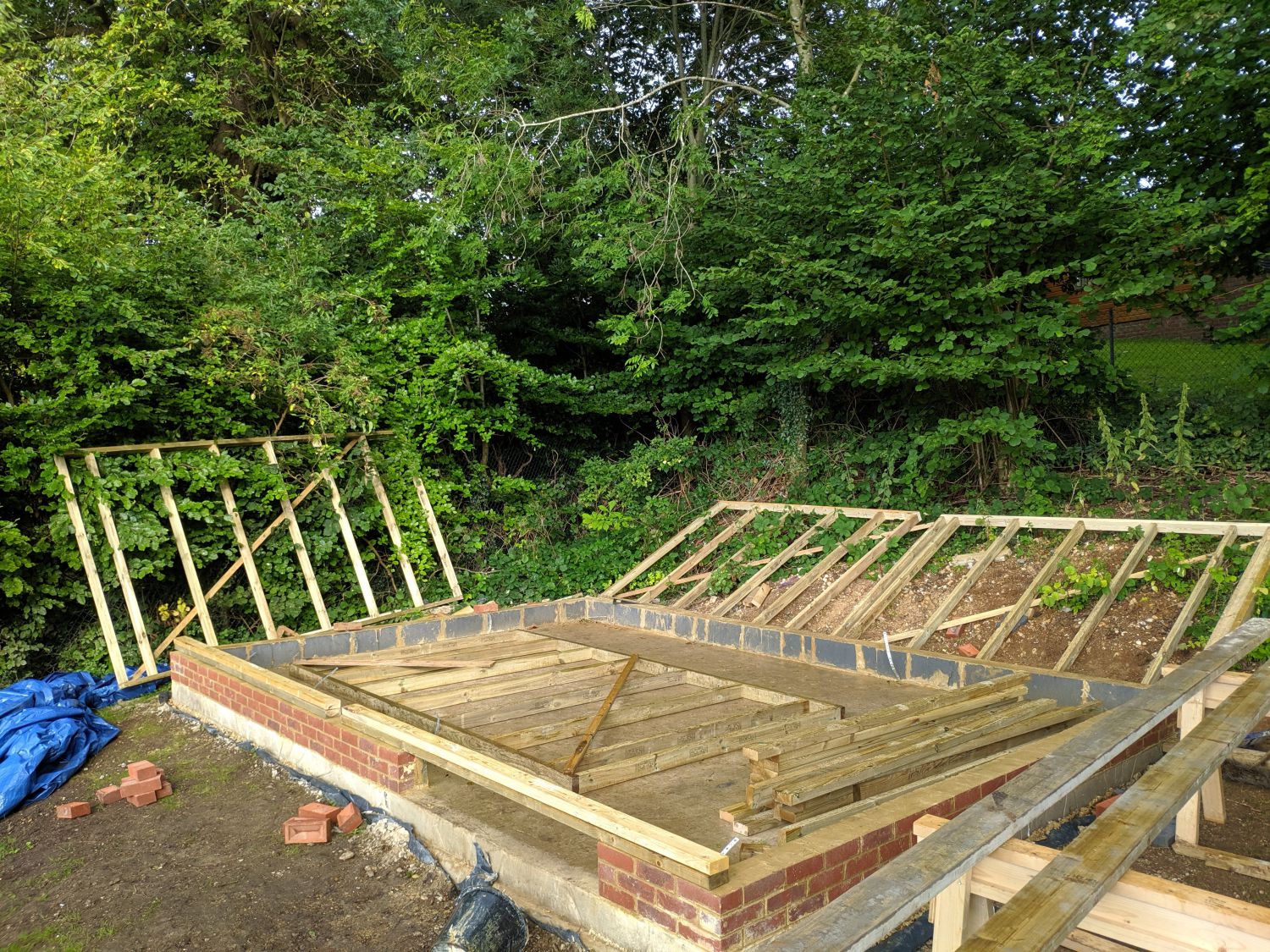
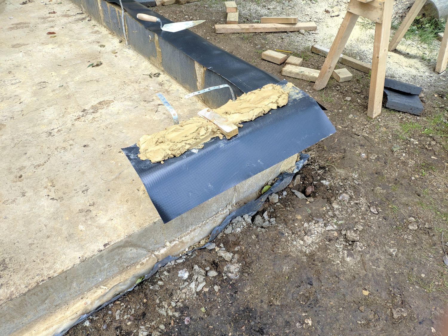
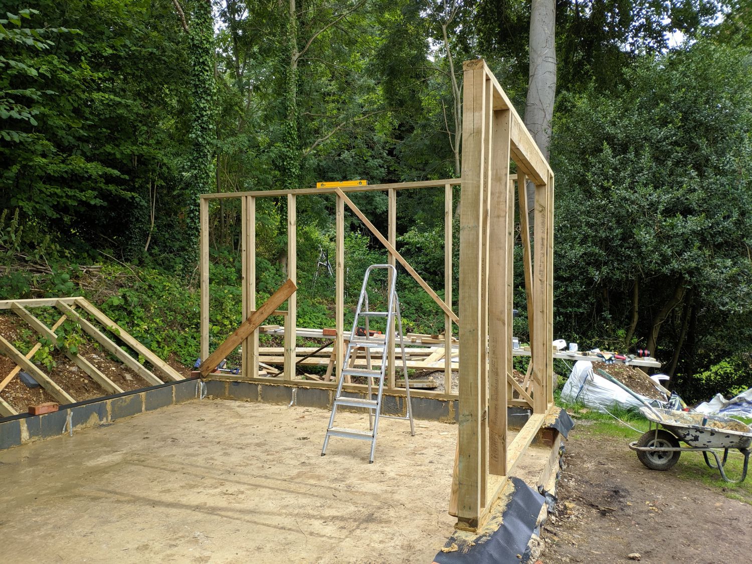
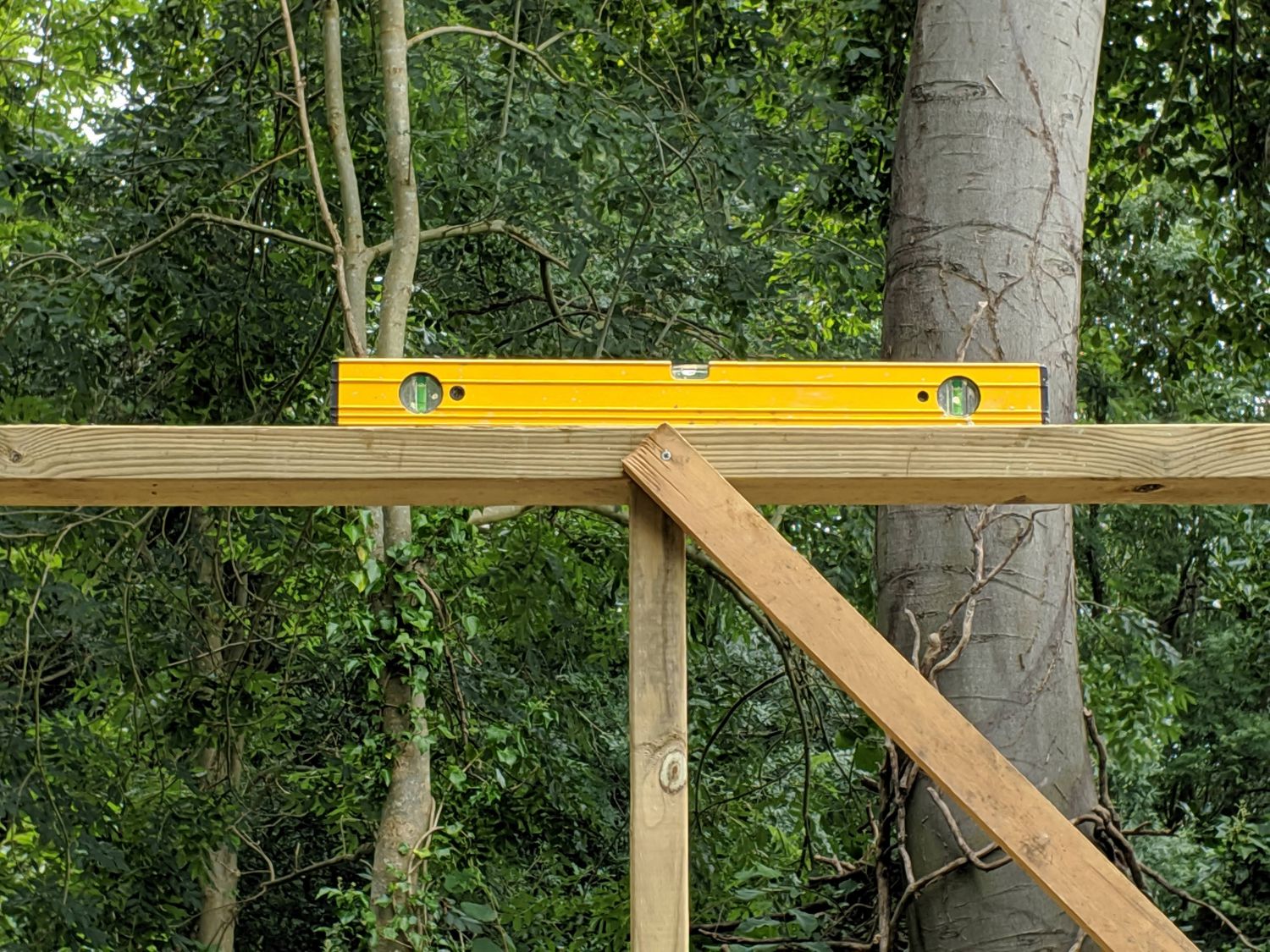
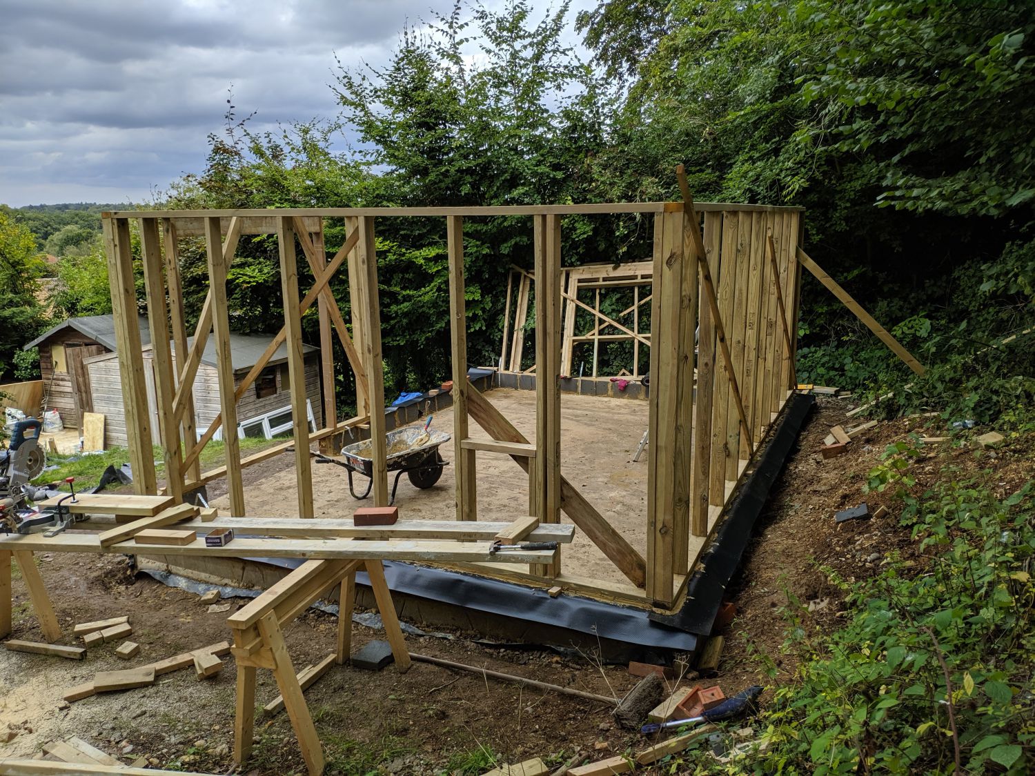
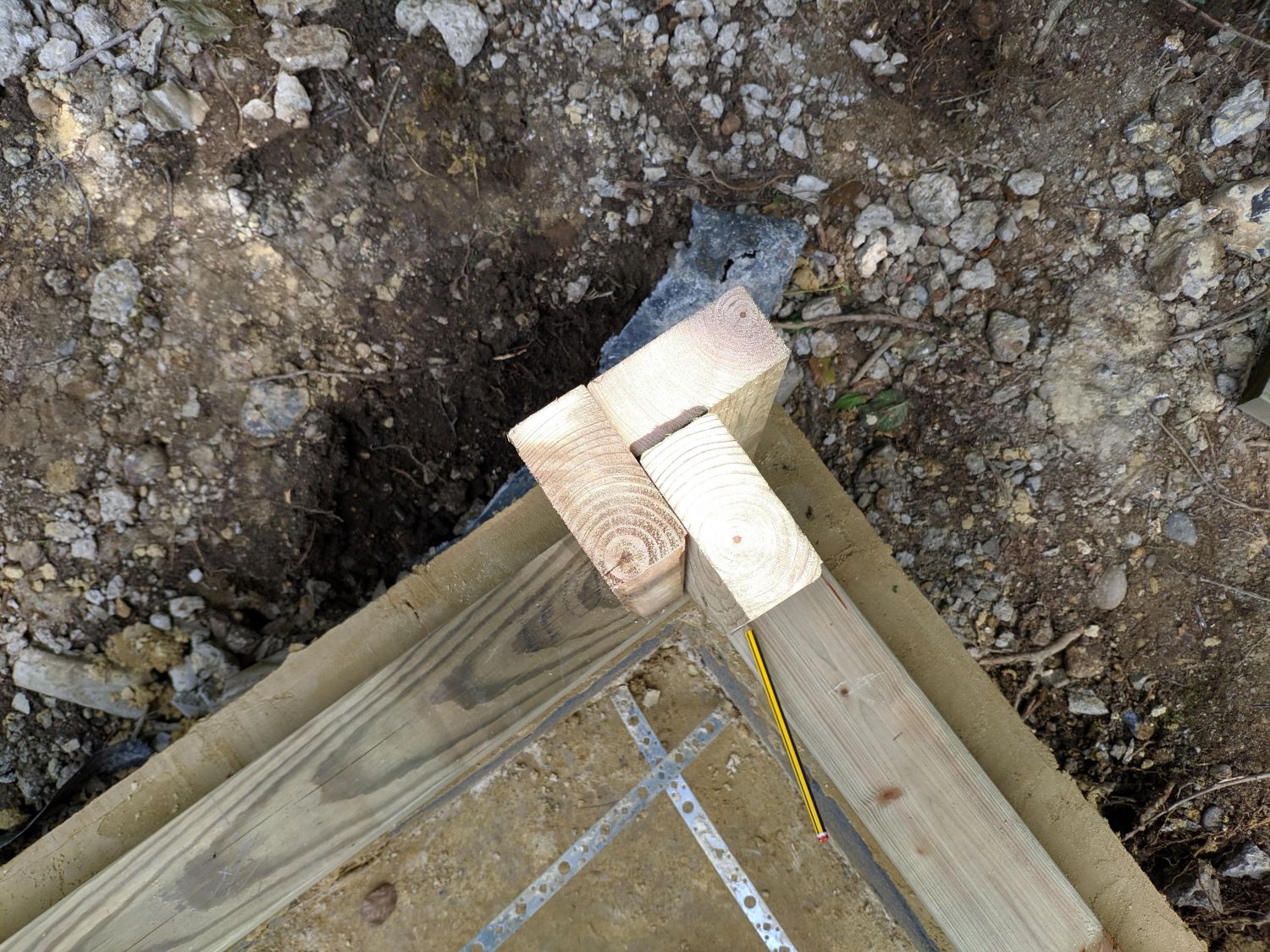
After mixing some mortar, I put down a bed and aligned the first wall segment atop it. I then used a mallet to adjust the wedges and ensure the wall was level before screwing down the metal strapping. I followed by doing the same for the second wall, ensuring 90°, then nailing the corners at regular intervals in both directions. Once two corners were up the structure was stable so the rest were much more straightforward.
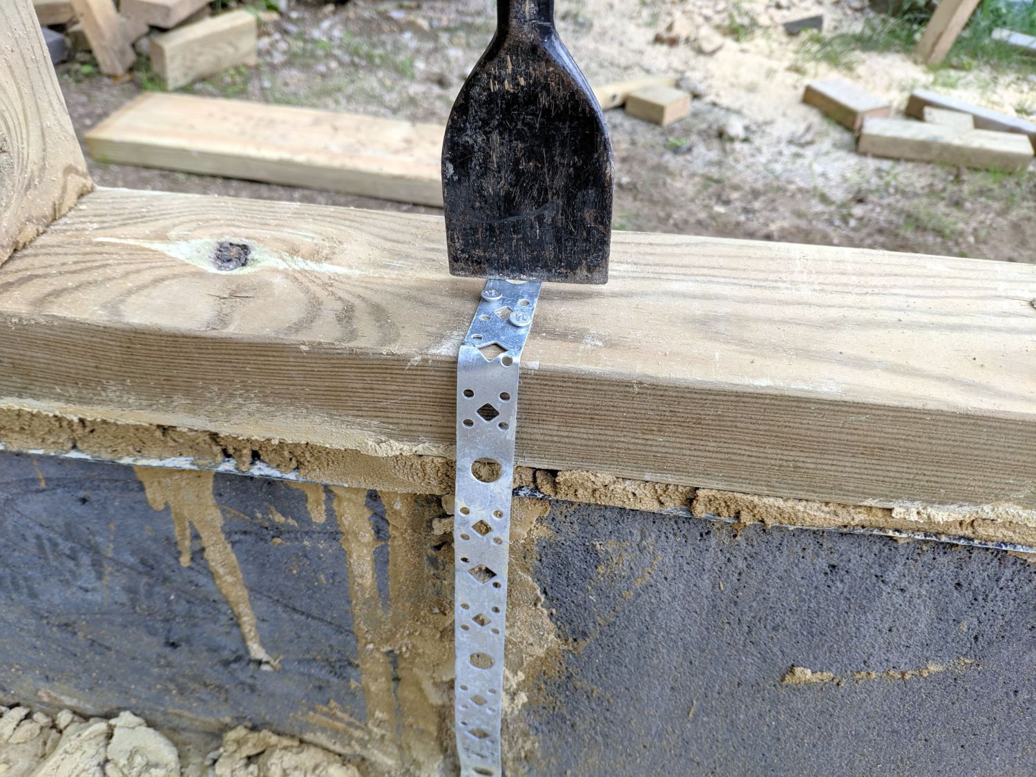
After all the walls were in and the mortar had dried I removed the wedges and cut the metal strapping to length. I then nailed in the double top-plate, ensuring the end joints were offset from the plate below. Because I chose to use a double top plate the joists do not need to sit directly above wall studs.