
To finish the rover circuit I needed to solder it together, test it worked as expected and install it into the chassis. To see how I researched and designed this board, see the previous posts.
PCB manufacture
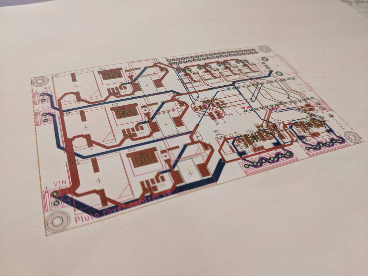
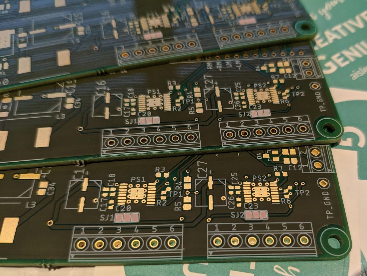
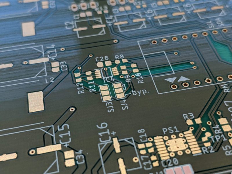
Before sending the board off to be made, I printed out a scale photo to ensure parts were correctly sized and connectors would fit as intended. The board was manufactured with 35µm copper and ENIG plated contacts.
Soldering
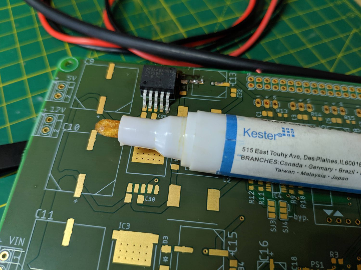
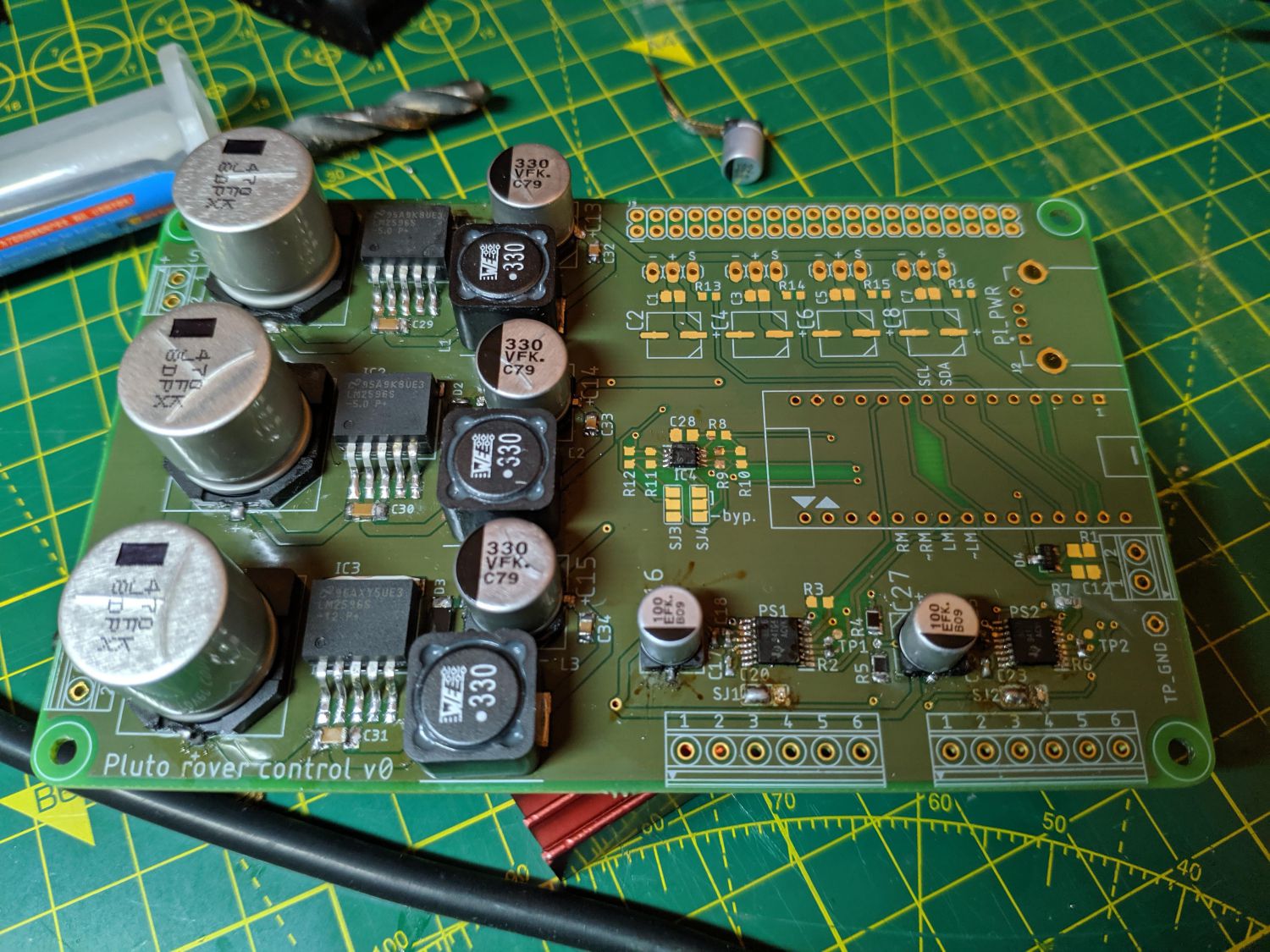
The small components and SMT packages made the soldering challenging. I used tweezers to move components into place and a fine solder tip so I could heat up individual legs where required. Additionally, I used leaded solder which has a lower melting point and flows more easily than alternatives. Flux was applied to pads and component legs before joining; this cleans each surface and prevents oxidation during soldering.
After soldering each section, I cleaned off excess flux with 99.9% isopropyl alcohol.
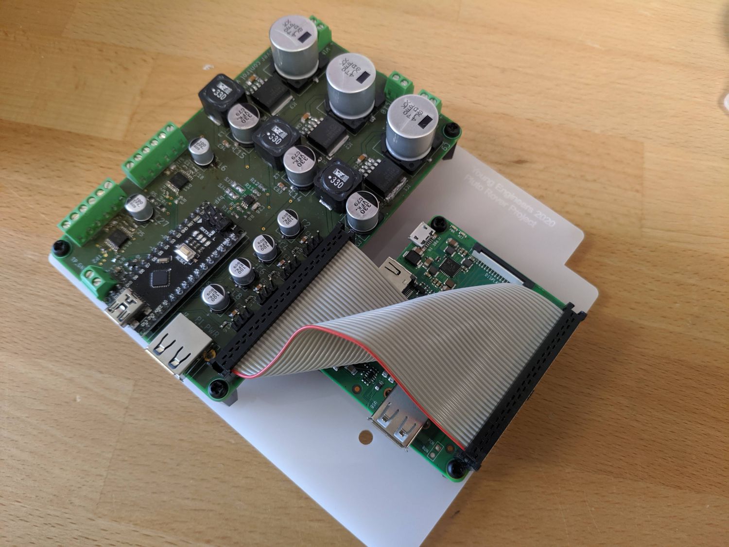
Motor drivers
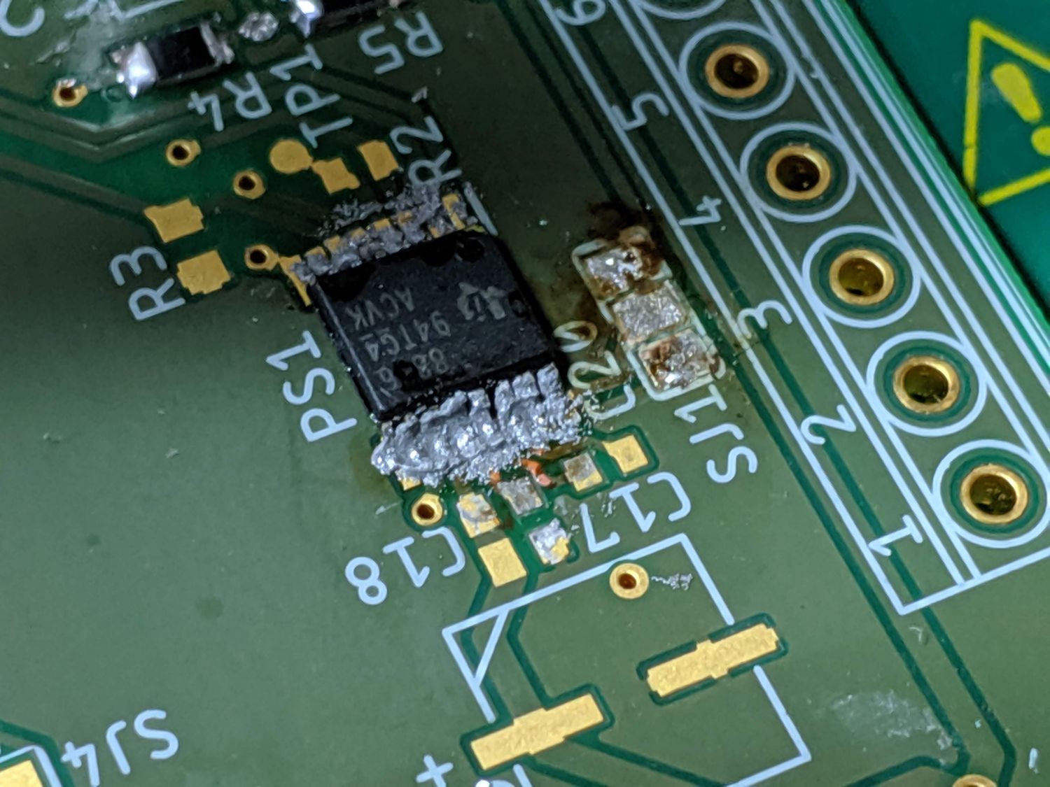
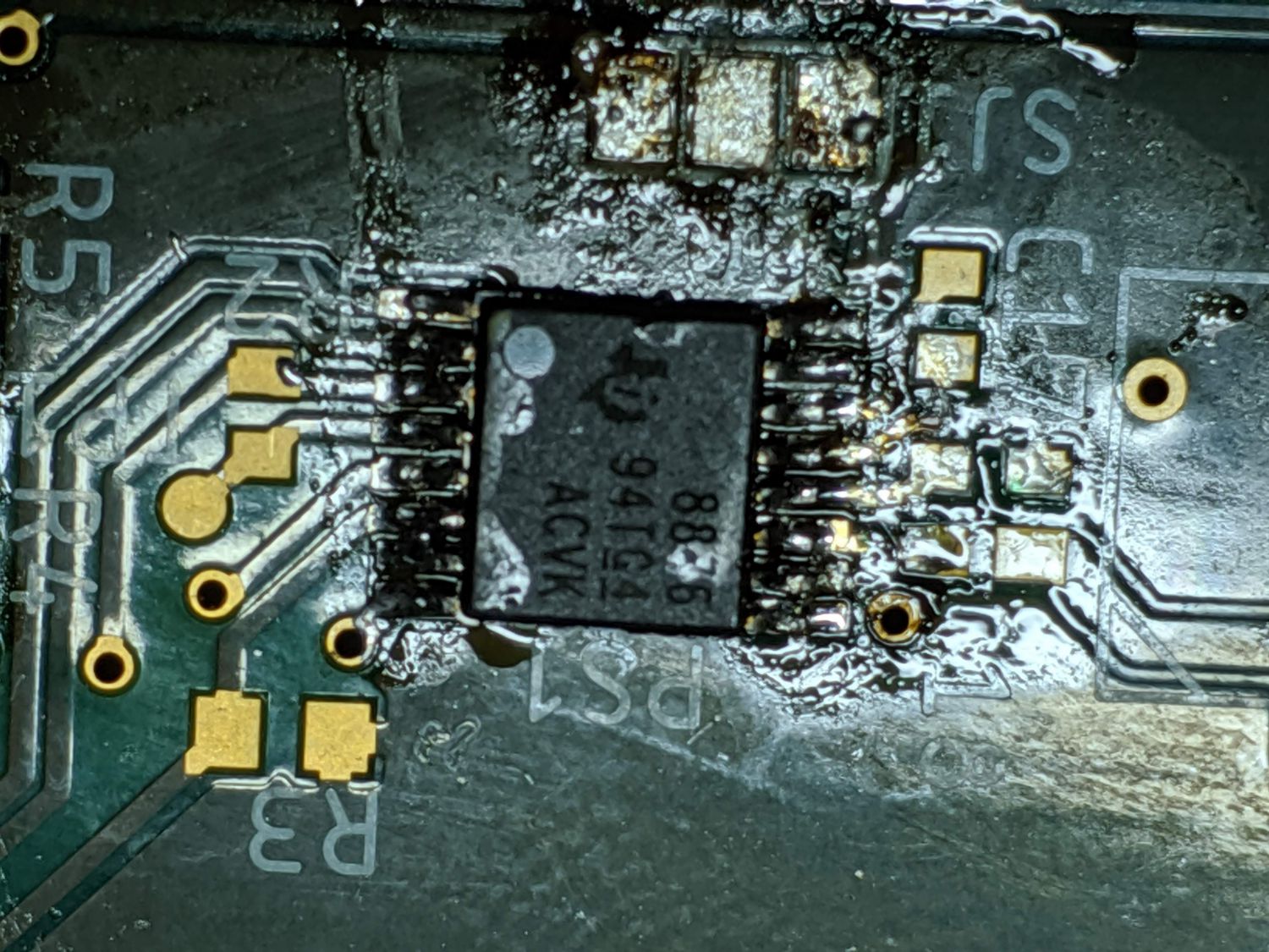
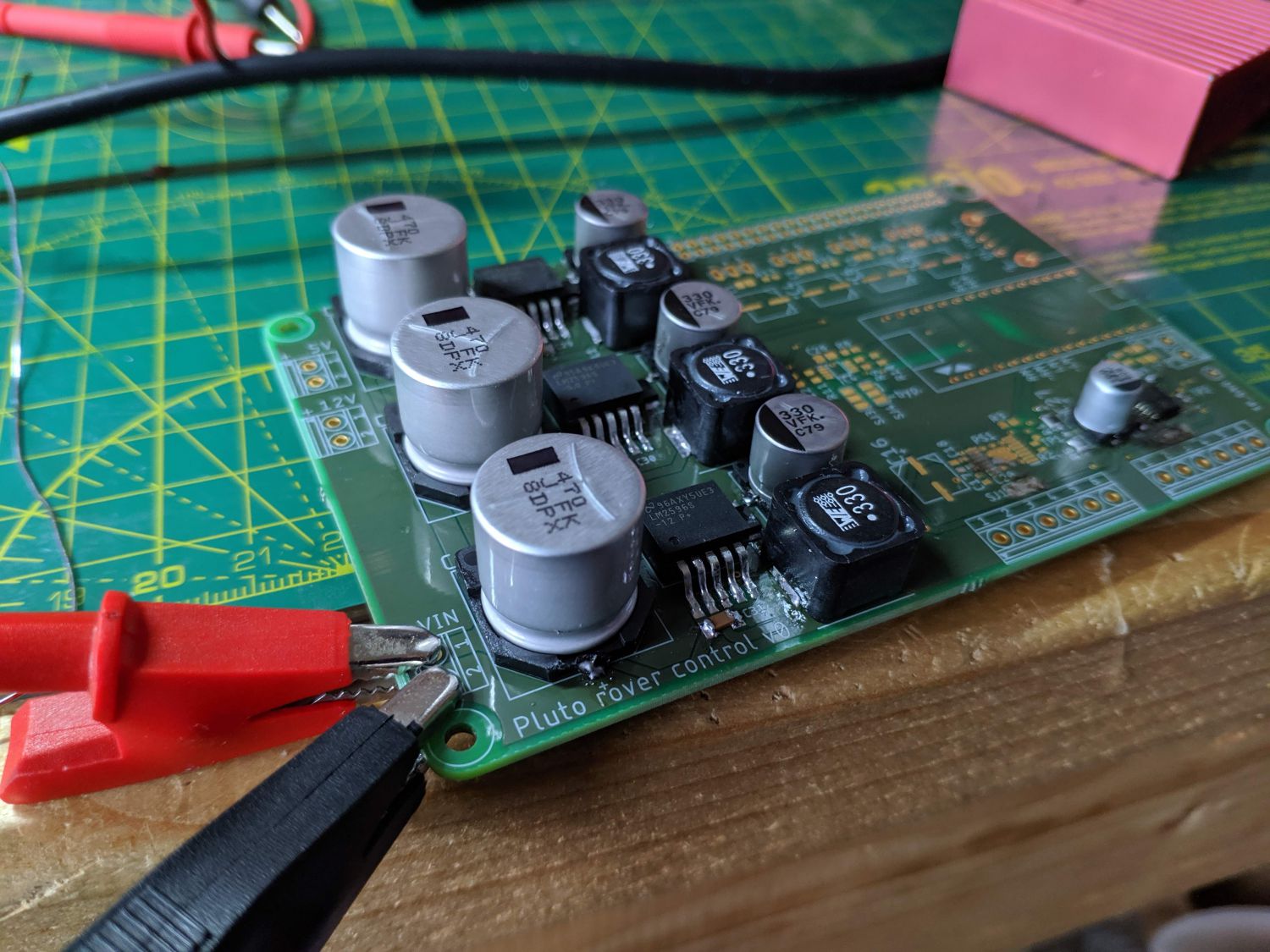
I began by soldering one of the motor drivers. This presented an interesting challenge as it had a non-visible pad on the bottom for heat dissipation; this pad is electrically connected to the ground pour. I applied solder paste to the pad and flooded the board with hot air, before applying a directed stream of much hotter air to the driver. Soon the pad reflowed and I moved on to connecting the legs.
At first I attempted to ‘drag solder’ the legs; I created a well of solder on my iron and dragged it slowly across the driver pins, allowing the solder to form joints on each pad. This worked well for one driver but did lead to some bridging which I had to remove with solder wick. On the next driver I experimented with using solder paste which made all of the connections first time.
Power supplies
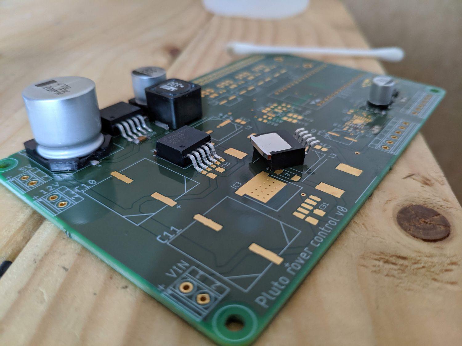
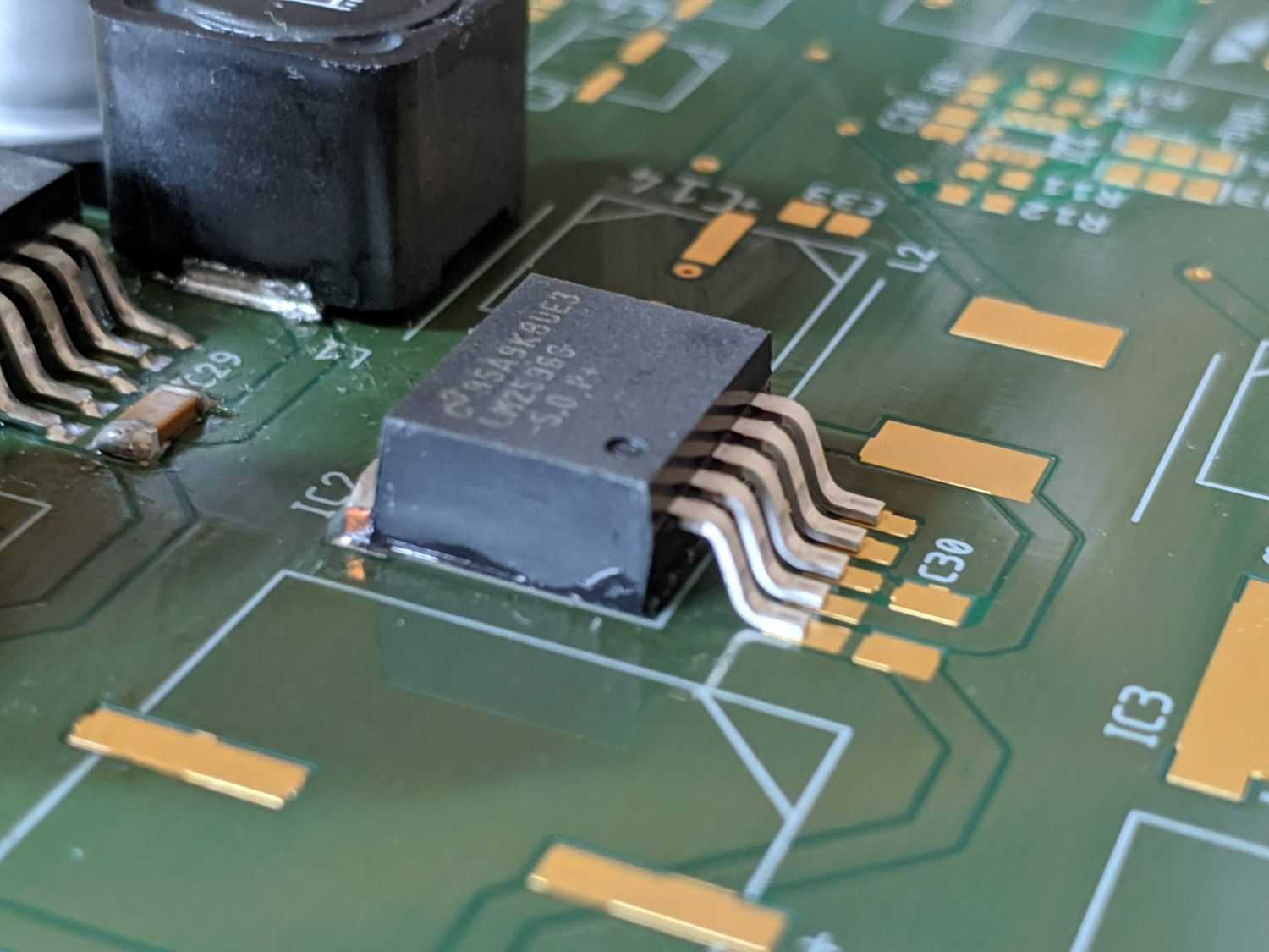
Like the motor drivers, the buck converter ICs also included a heat dissipation pad. This package was easier to solder as the pad could be heated via a visible tab; the shape of the pad also meant the ICs self-aligned after the bottom pad had been soldered.

Testing
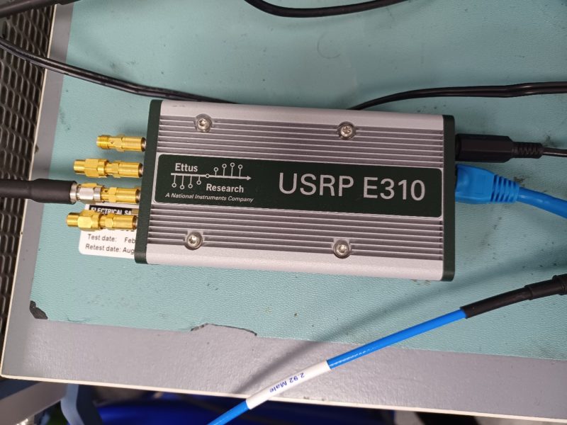
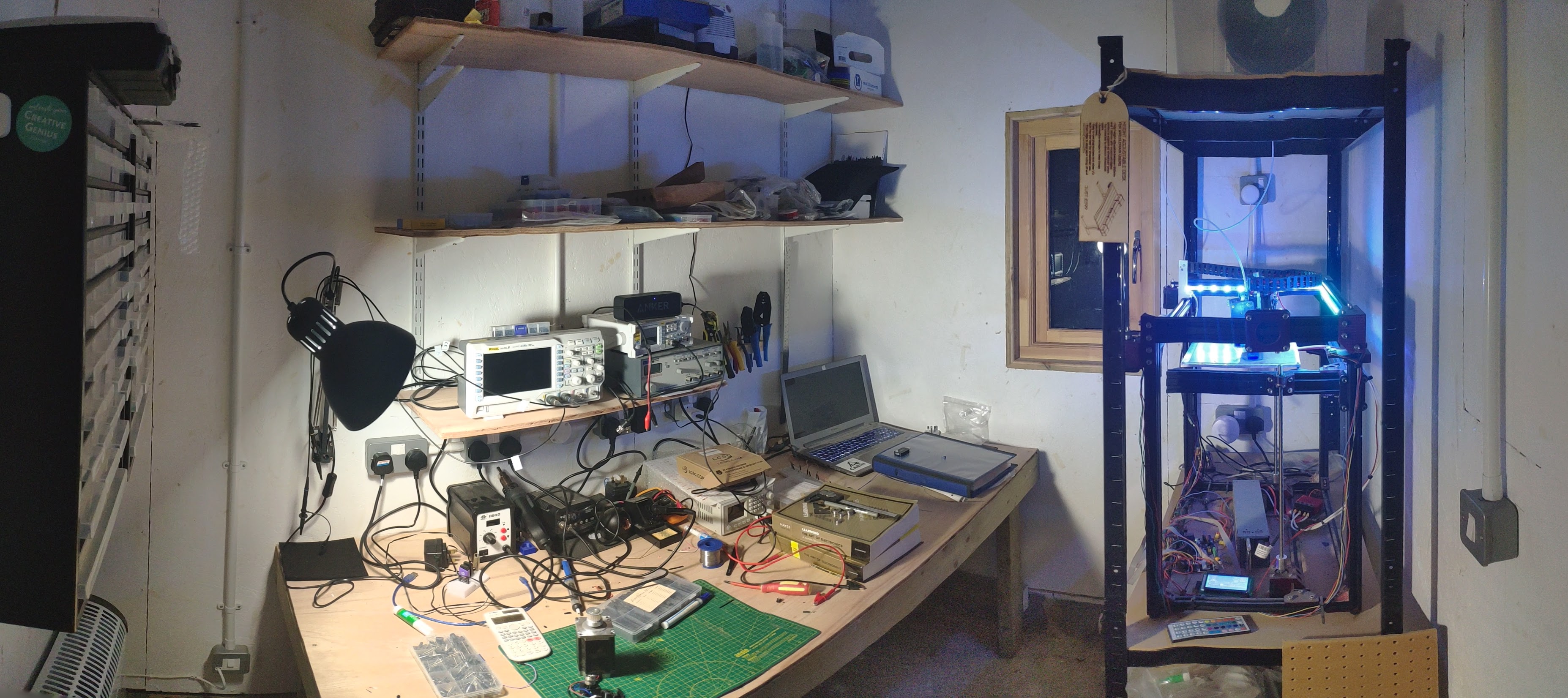
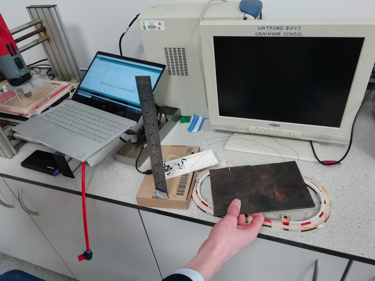
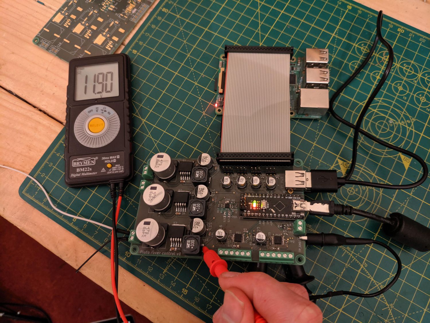
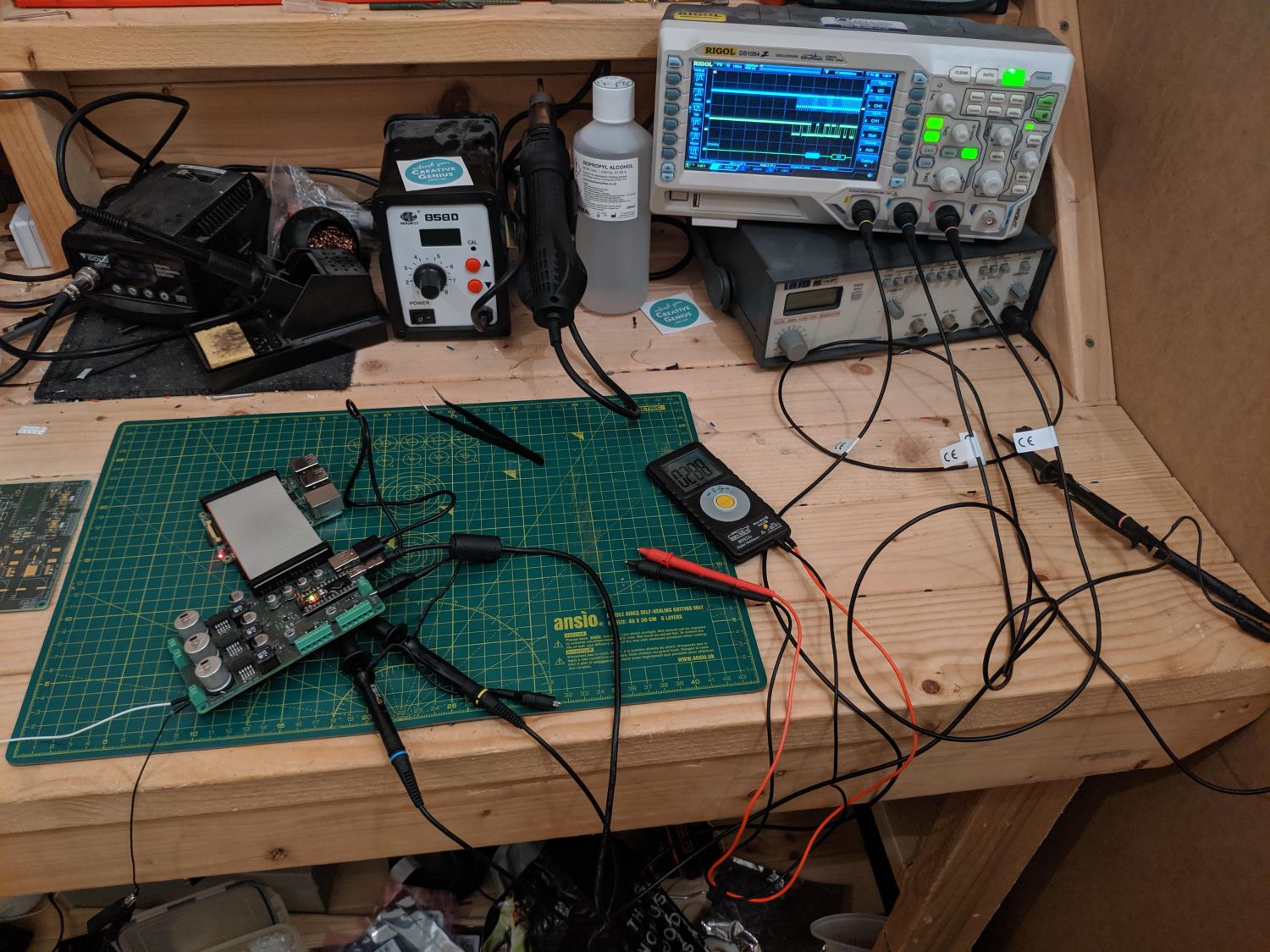
Throughout the assembly process I conducted unit tests to ensure each part of the circuit worked as expected. This included testing each buck converter as I finished soldering them, testing the motor drivers, testing I2C communication to the Pi and testing the metal detector.
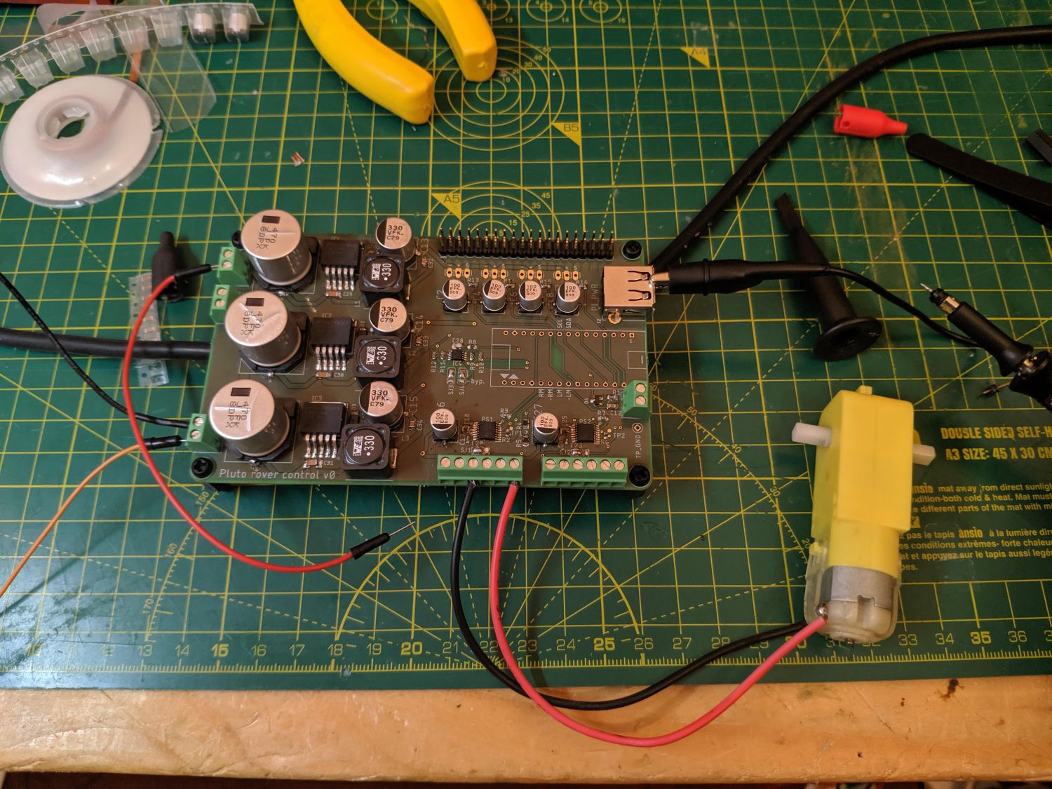
Initially, one of the motor drivers was unresponsive and entering fault mode. Fortunately, after reflowing all of the joints again with hot air, the driver worked as intended. Everything else worked as expected.
Conclusion
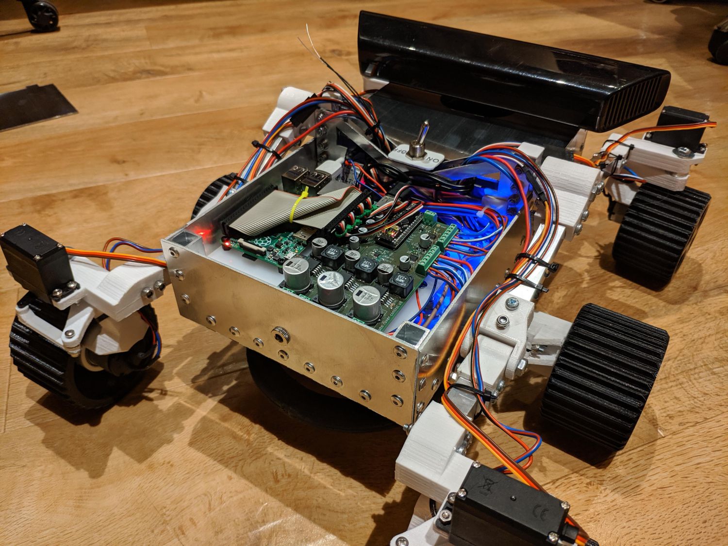
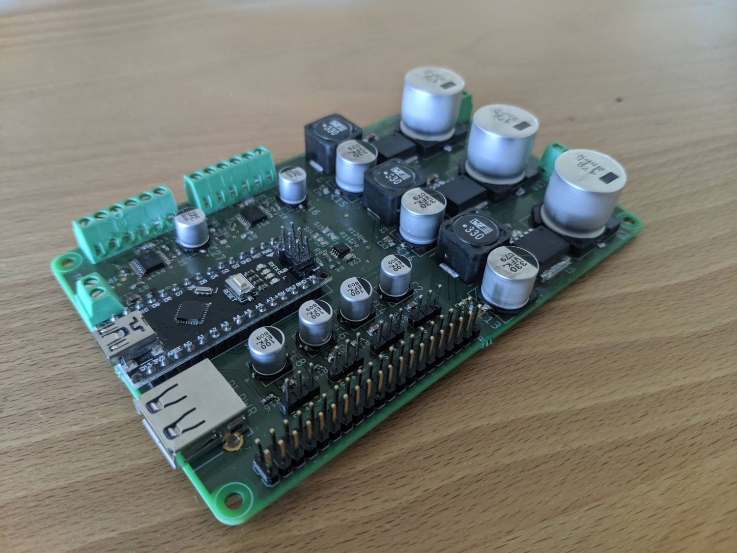
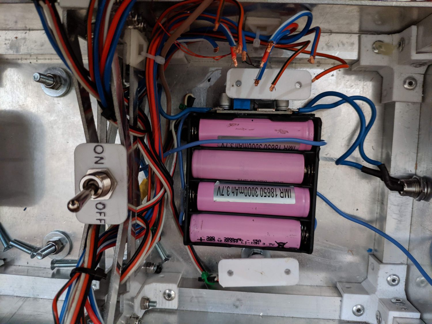
After mounting the Pi and circuit board to a custom mounting plate in the rover and wiring in the coil, motors and servos my job was done!
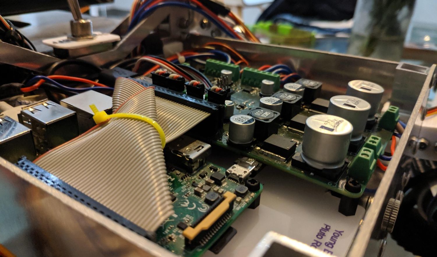
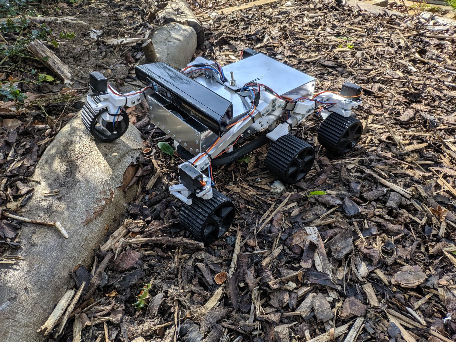
Overall I am very happy with the end result. The custom circuit board centralises all of the electronics, fully fulfils the specification and also looks fantastic mounted in the rover.
If you are interested in further details about the mechanical assembly of the rover, make sure to take a look at the project webpage. The CAD files and schematics for the PCB are also available on that page.
Thank you for reading.