For use of equipment and lighting, an electrical supply in the shed was a priority. Furthermore, I wanted to ensure I could use the building all year round so needed electric heating.
My whole electrical installation was done with the help of a qualified electrician. This was a legal requirement for adding the new circuit at the house, and sped things up hugely when installing sockets and lighting.
Planning
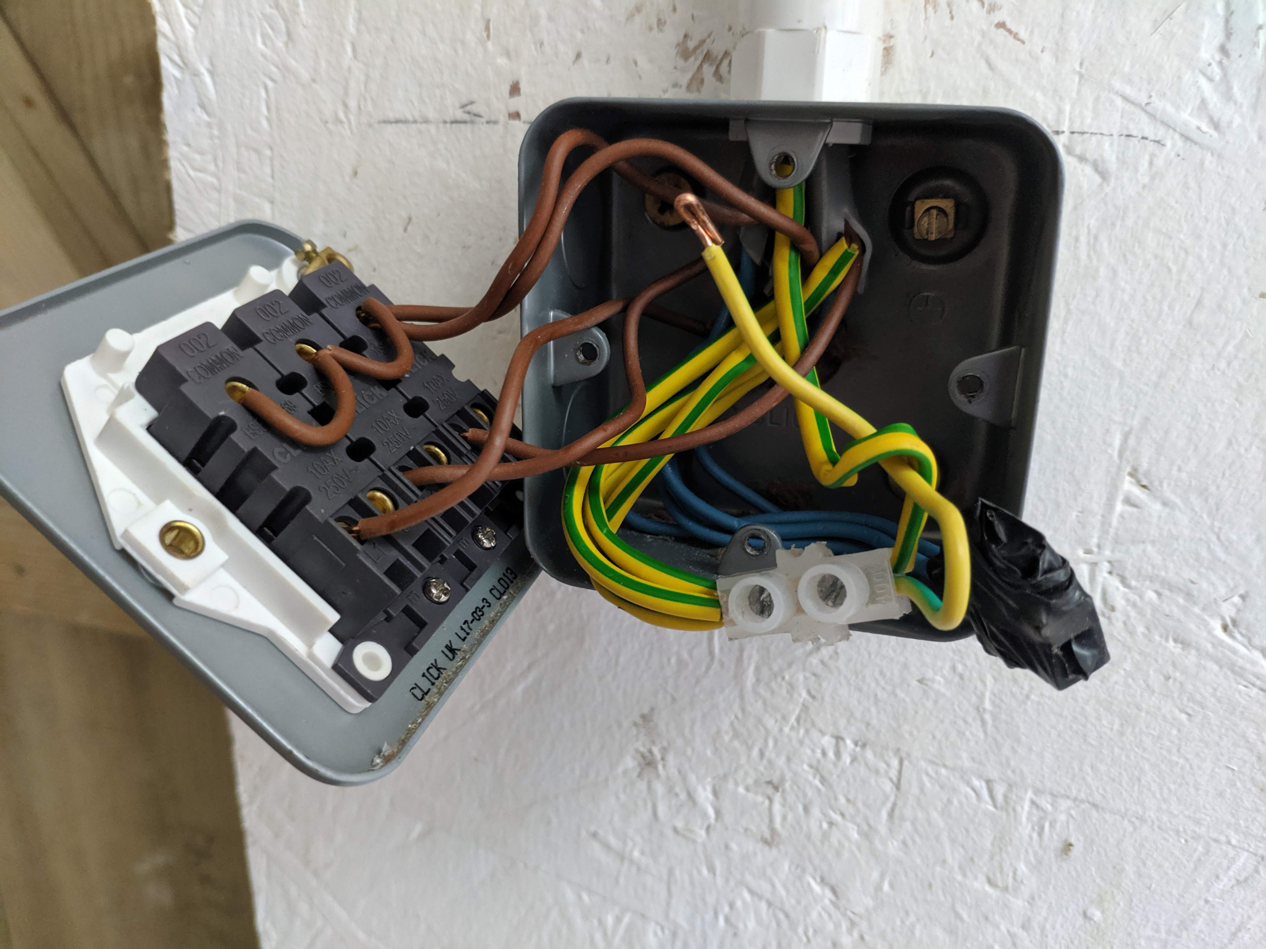
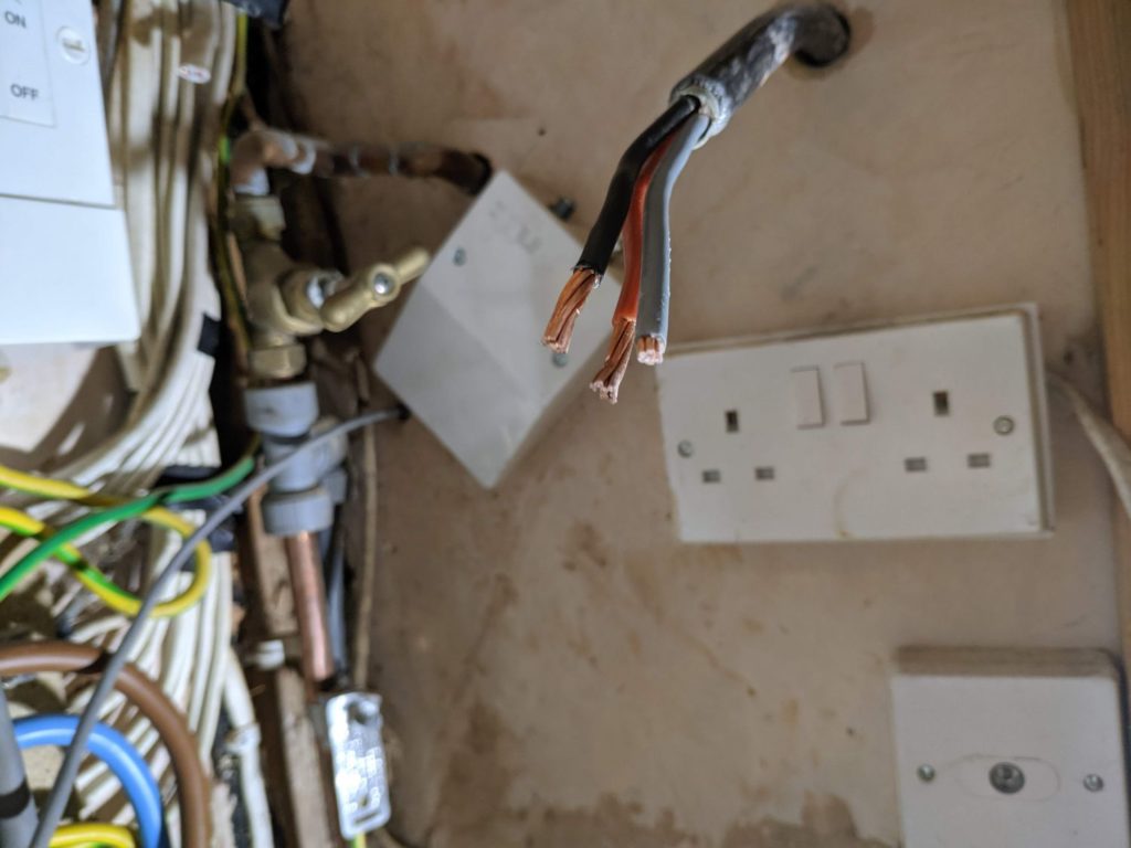
Because of the location of my building, the supply cable had to run up the garden. For this reason I decided to use steel wire armoured (SWA) cable which contains steel armouring strands that surround the core copper conductors. SWA can be buried or clipped to a structure but can also simply be run across the ground, which in this case was the most practical option.
I knew I might want to run machinery, extraction, heating and lighting at the same time so I chose the maximum circuit amperage possible to take off the main consumer unit at the house side. The house is supplied with 100A, so a 50A breaker to the shed was selected; this should be plenty and was based off calculations for heating, lighting and socket usage. The circuits were organised as follows:
- 32A ring main circuit:
- 13x double sockets
- 2x single sockets
- 20A heating circuit:
- 2x 2kW convection heaters wired into fused spurs
- 6A lighting circuit:
- Triple switch controlling main lights, attic lights, external lights
- Single switch controlling electronics room lights
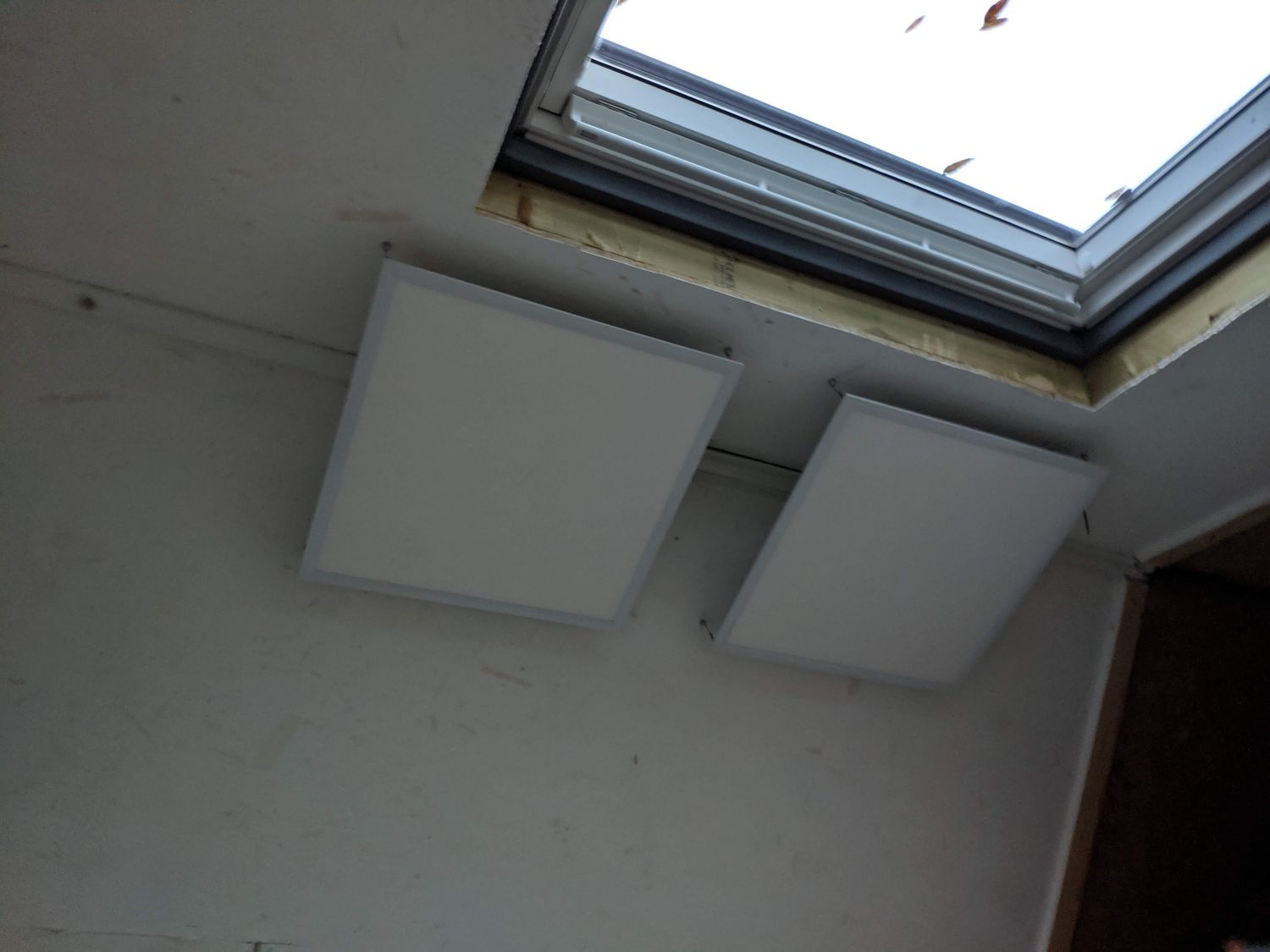
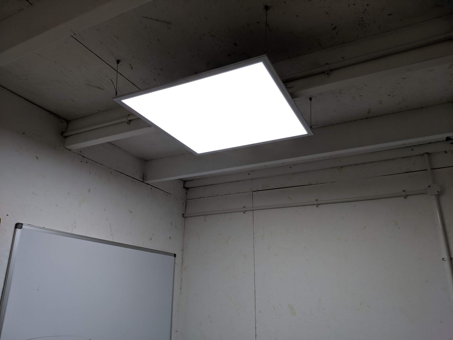
- 3x 40W LED panels to light main room
- 1x 40W LED panel to light electronics room
- 1x 20W LED tube to light attic
- External lights
These circuits are all connected in a secondary shed consumer unit where the SWA also terminates. MCBs (miniature circuit breakers) switch and protect each circuit from over current.
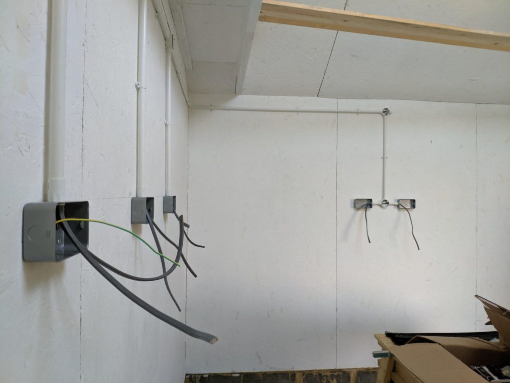
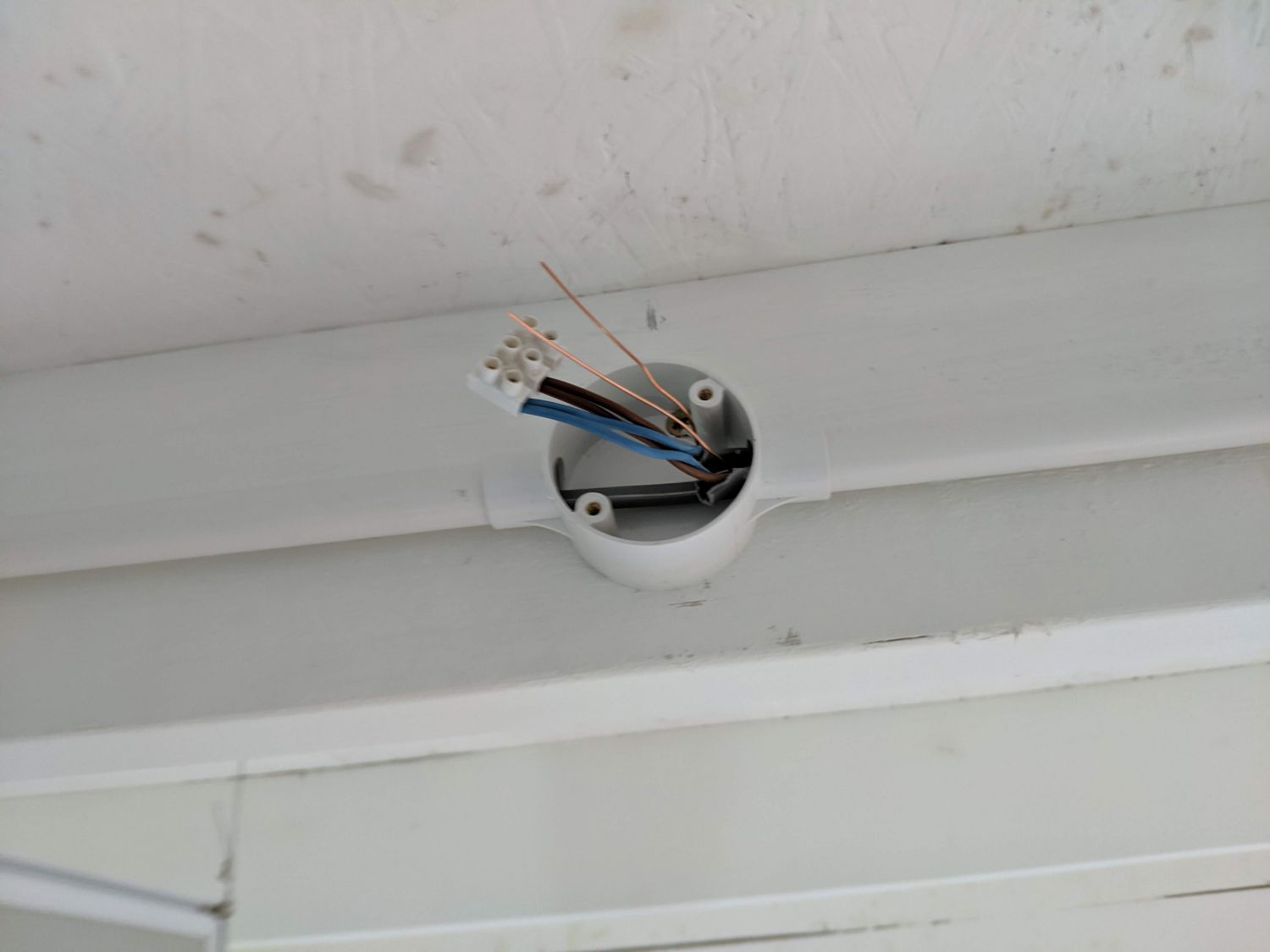
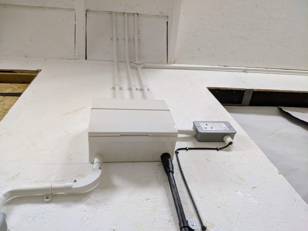
Initially I considered running the circuits ‘clipped direct’ to the walls of the shed but was later persuaded by my electrician to place the wires in PVC conduit. These are designed to terminate at back box ‘knockouts’ perfectly and run into junction boxes where the ring main can branch off. Bending the conduit is simple and can be done by hand; a spring is placed in the pipe on the bend to prevent collapse and a rag is used to friction heat the PVC before shaping.
I decided to pick metal clad switches and sockets throughout the workshop as they are more resistant to bashes and look brilliant.
Socket ring circuit
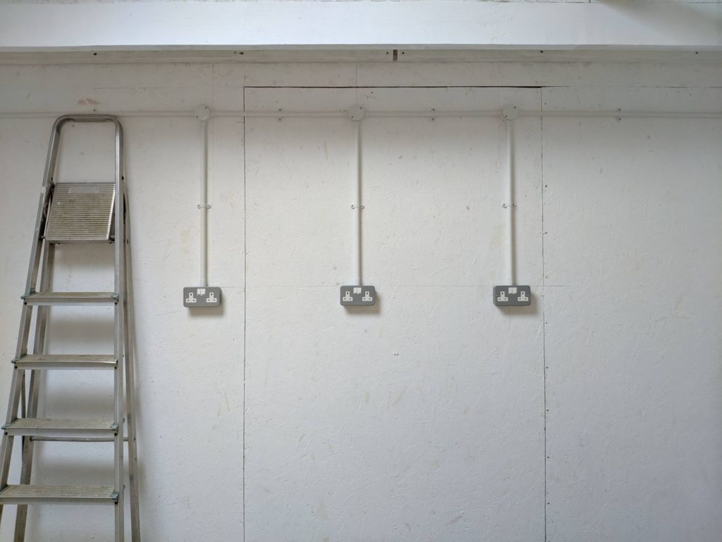
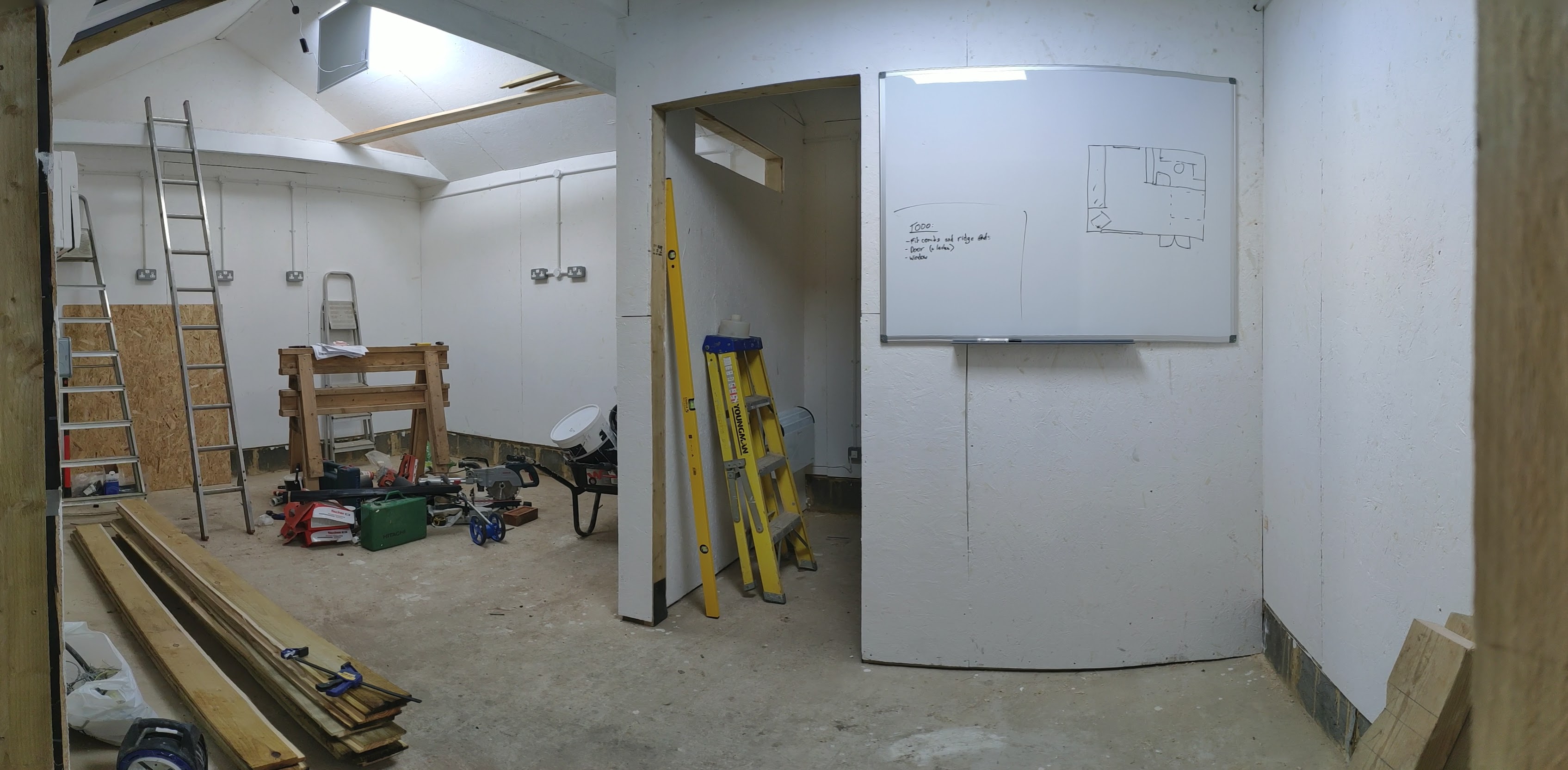
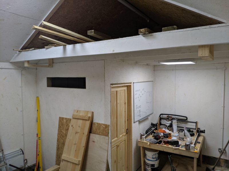
To begin, we installed the socket ring which contains all 15 socket boxes. The conduit was run close to the top of the walls and most sockets were installed at eye level to keep them out of the way of workbenches and tools: this has proved very practical so far. Some sockets were installed for specific purposes such as a low single gang for my CNC machine, but I also tried to ensure power was accessible everywhere in the workshop for portable tool use.
The sockets are on a ring circuit so T&E (twin and earth) cable has to be run both down to each plug and back up; if any part of the ring is broken, the sockets can still function as normal. In some locations, such as for the plugs under the window, it was easier to take a ‘spur’ off a socket already on the ring by running a single T&E between the two boxes.
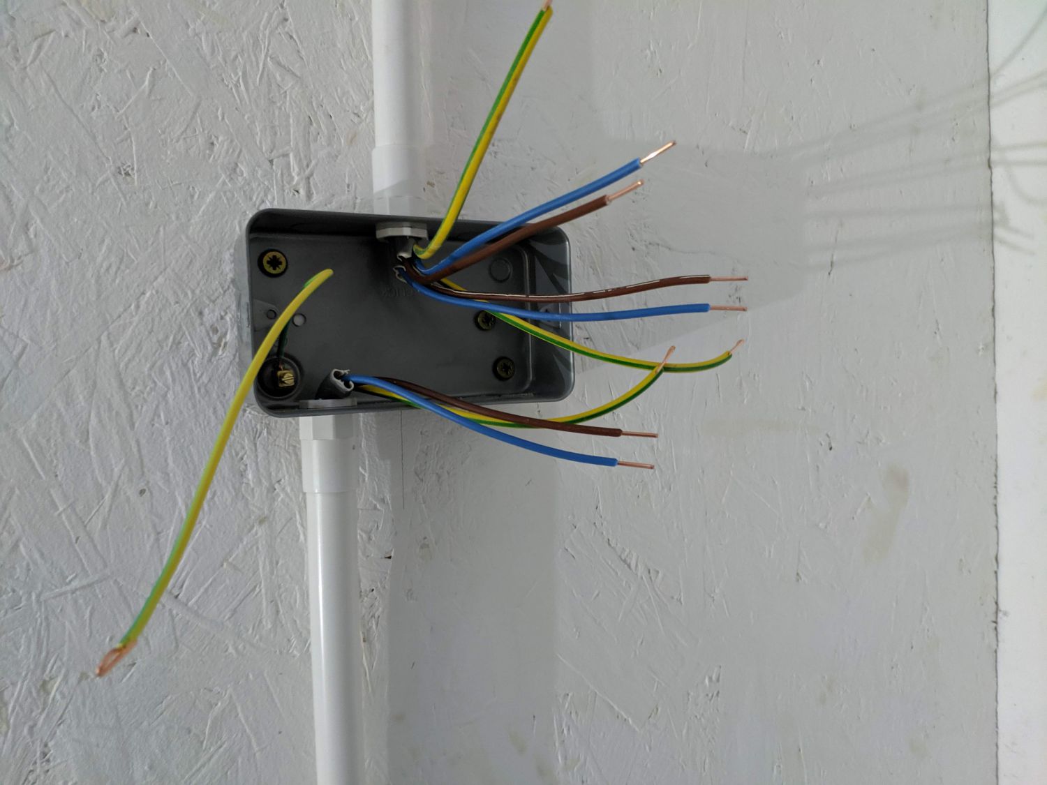
Once wires were run to each back box we stripped back the ‘jacket’ exposing the individual conductors. The insulation for each conductor was then also removed leaving the bare solid cores to be screwed into the sockets. In some cases it was necessary to fold the copper core back on itself so it was properly held in the terminals. Each back box was bonded to earth through the pre-installed earthing lug: this is good practice even if the box is already earthed through the screws into the back box.
Interior lighting
The shed has a total of four switched lighting circuits, all on a single breaker. All lights were one-way switched.
I ran a T&E to each switch back box and wired the live wire into the common switch terminal. I then ran another T&E from the switch to the light, connecting live to L1 of the switch and bonding all neutrals to a terminal in the back box of the switch. This ‘switched live’ setup means the live wire is disconnected from the lights when the switch is thrown.
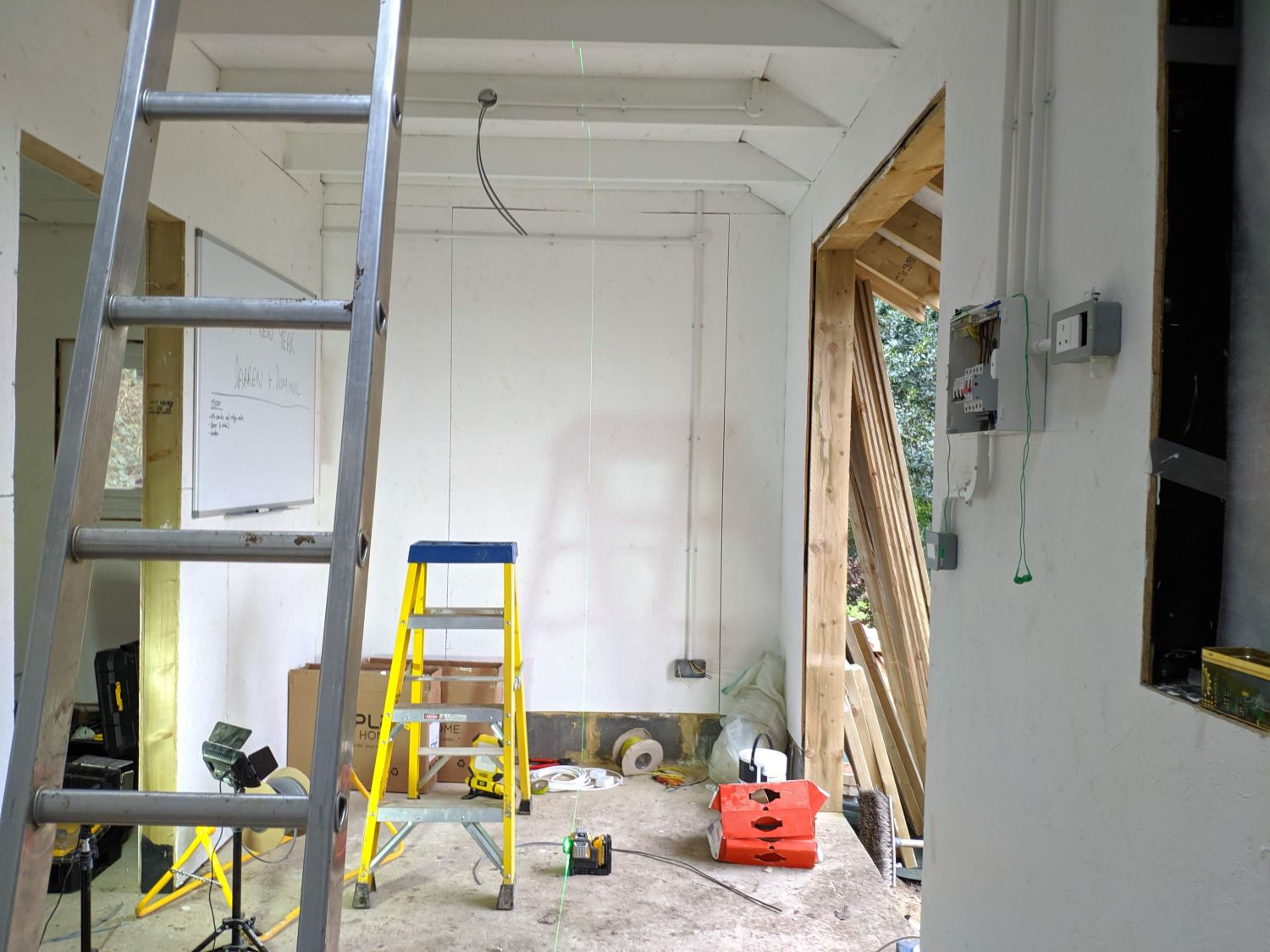
To line up the conduit as it ran down to switches and other back boxes we used a laser level. This automatically aligns itself to the vertical and projects a line across the walls in all directions.
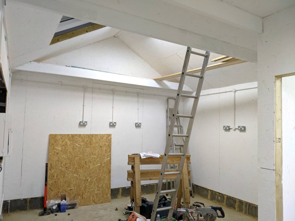
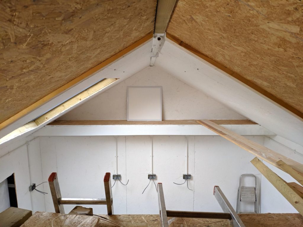
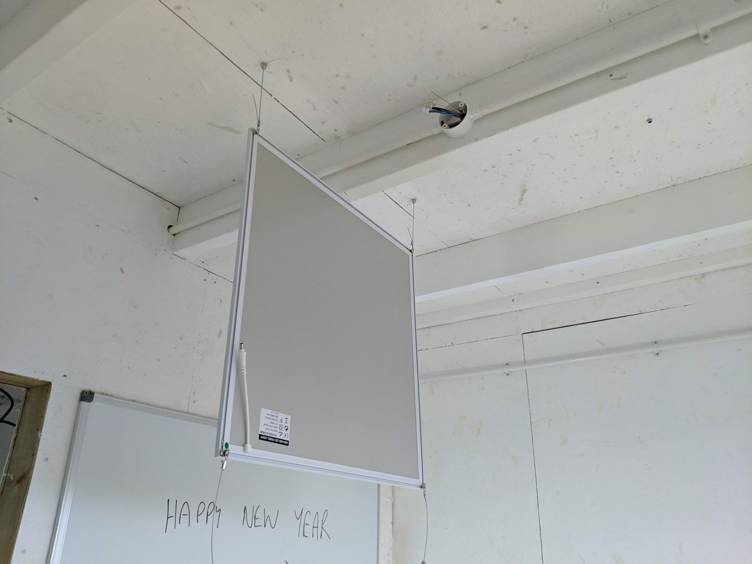
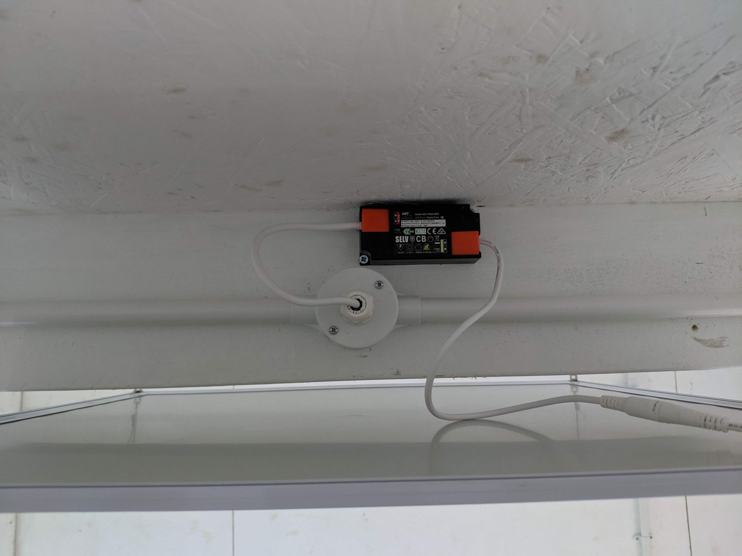
The LED panels required drivers which were mounted to joists above them. The panels themselves are hung from the ceiling with steel wire terminated at the roof and screwed in place. In the attic area I instead opted to use an LED batten mounted to the ridge. This fits well and allows for quick replacement if the bulb ever fails.
Heating
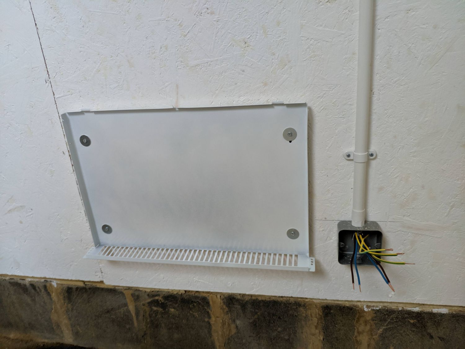
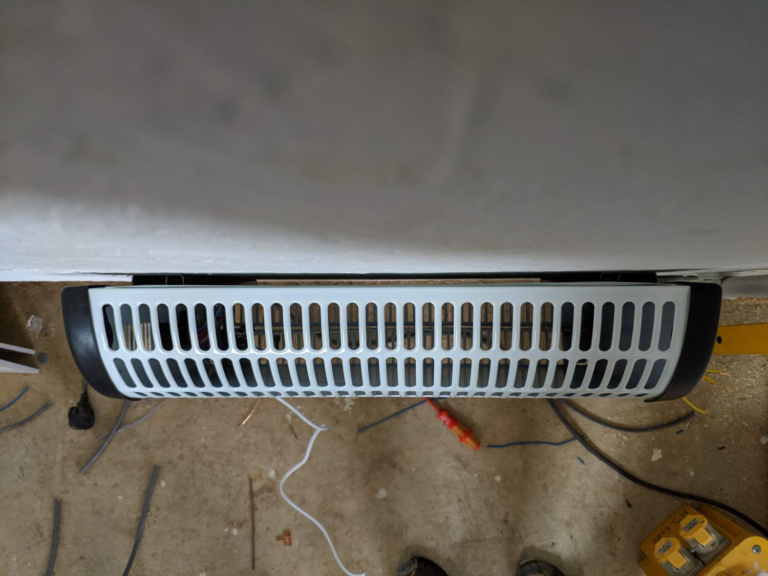
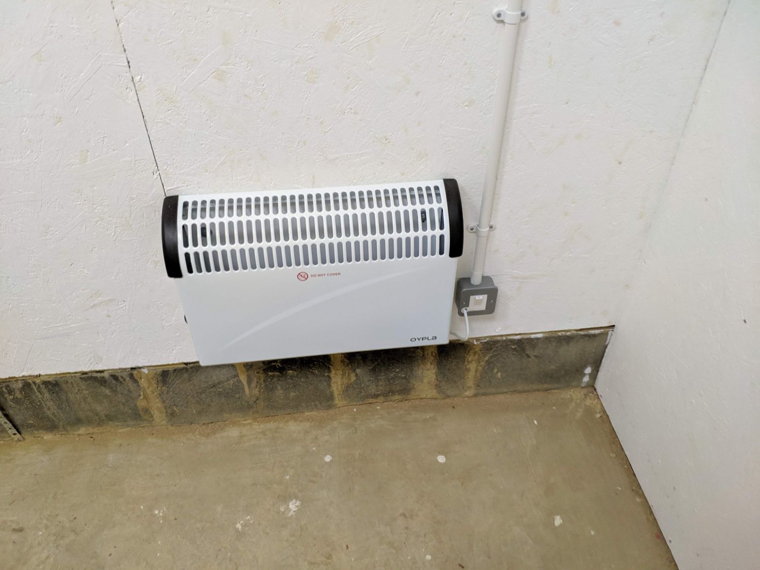
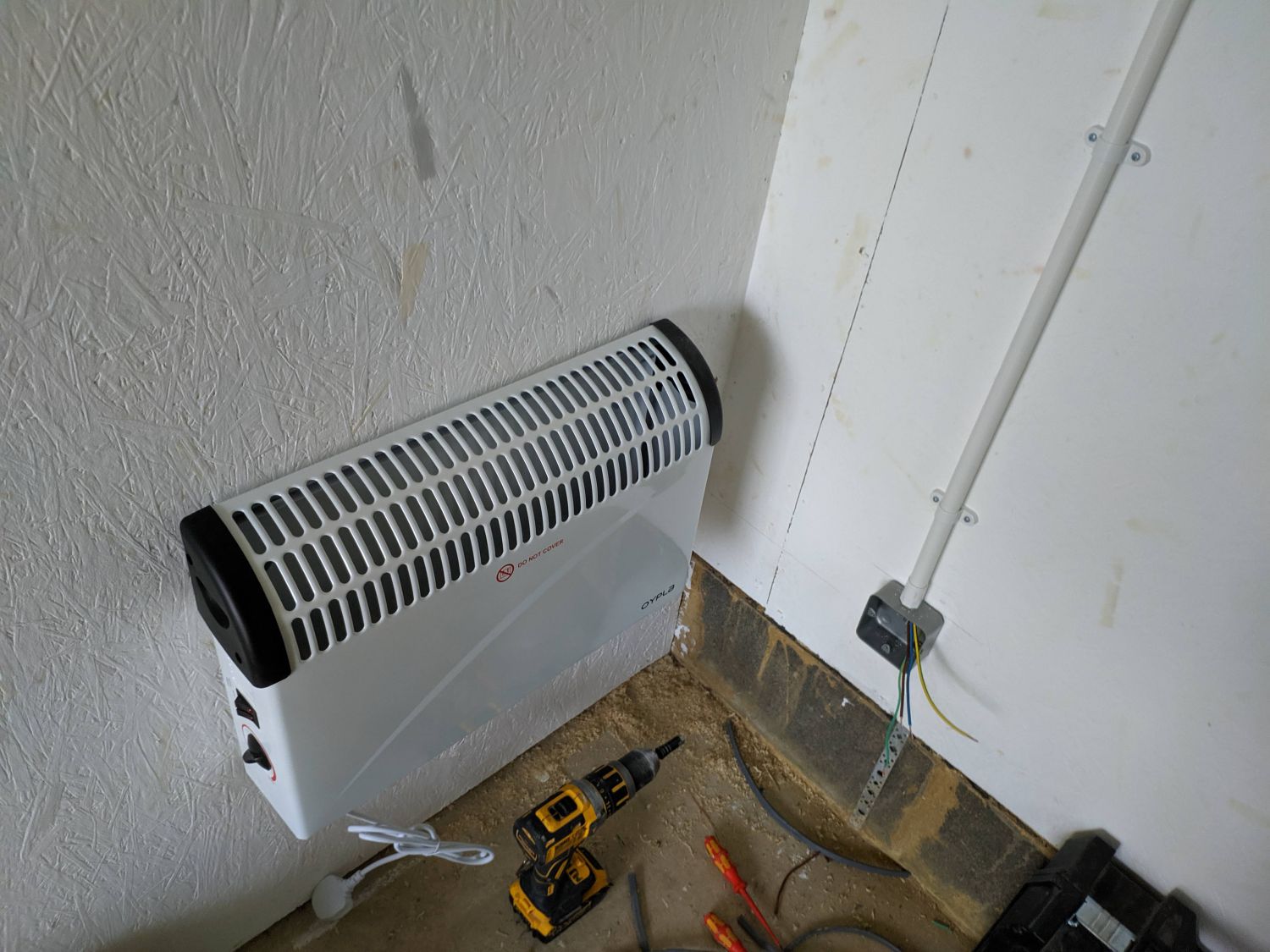
Heating is provided by two inexpensive 2kW convectors. They are wired on a separate 20A circuit breaker and supplied via a direct line from the consumer unit. By placing the heaters on each side of the interior wall I minimised the length of cable required; especially important as the T&E had to be crammed in the same conduit as the ring circuit.
Fused spurs were installed to switch the heaters and provide overload protection.
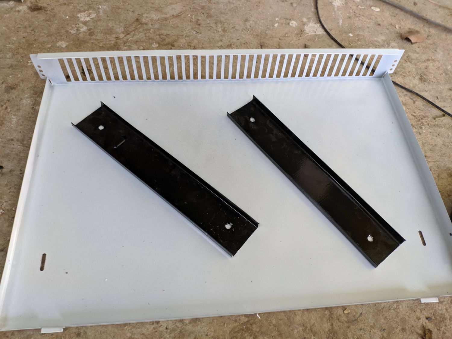
The heaters did not come with a wall mounting system (despite suggestions in the description!) so I instead cut down some scrap channel iron and screwed it into the wall. The back of the heaters were bolted to these channels: this gap ensures there is airflow around all sides of the unit.
Consumer unit and house connection
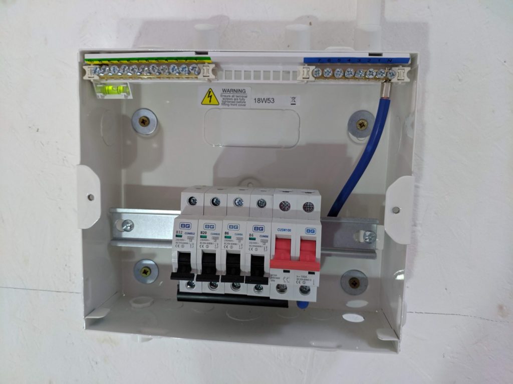
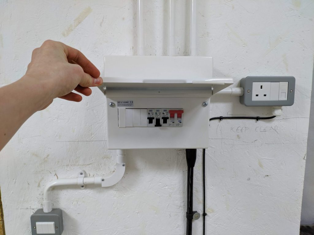
The secondary consumer unit is where all the MCBs are housed and electrical distribution for the shed takes place. All earth and neutral connections are bonded together in busbars across the top of the unit, live connections enter at the bottom of each MCB.
At the house end an RCD (residual current device) shuts off the supply if a certain difference between the current through the live and neutral wire is reached. A double pole switch, connecting both the live and neutral wires, is present in the secondary consumer unit. This can be used to isolate the shed if electrical work is being done.
The MCBs themselves behave like resettable fuses, tripping if their maximum current is reached which likely indicates a fault in a connected device. The current rating of each is chosen based on the typical draw of the circuit, plus some headroom.
The unit contains knockouts for termination of both 20mm conduit and SWA. We ran most of the T&E cables up into the loft area for distribution behind the loft reveal and down the edges of the gable.
The SWA and ethernet cables were run up next to the garden fence. To protect the ethernet cable from UV degradation and weather it was sleeved in a ‘Kopex’ style conduit. At the house end we drilled a hole through the wall directly into the consumer unit cabinet and wired the armoured cable into a junction box before being attached to a 50A MCB. There was already a route into the shed for the cables via conduit I had cast into the slab.
Conclusion
With the supply wired in I could finally stop dragging three extension cords up to the shed each time I was in the workshop. The LED panels have been working fantastically and I am definitely happy with the number of sockets I installed (though have actually used them up in the small room).
I later installed three external lights when cladding the building.