As part of a school project I was tasked with designing a miniature pinball machine, this post details the design and construction process.
The scope we were given was quite wide but there were three key requirements:
- maximum size of 400 x 500mm
- must have at least 2 different mechanisms
- use at least one hand tool and CAD/CAM in the making
Design
Initial ideas

I began the project by researching pinball machines, how they work and typical mechanisms and features included on the play-field. Almost all seemed to have electromechanical flippers, ‘pop’ bumpers (that projected the ball on contact), and slingshots (that fired the ball on contact). I knew I wanted to include these features in my pinball machine, which would involve adapting the mechanisms included in larger machines to make them suitable for a smaller application.
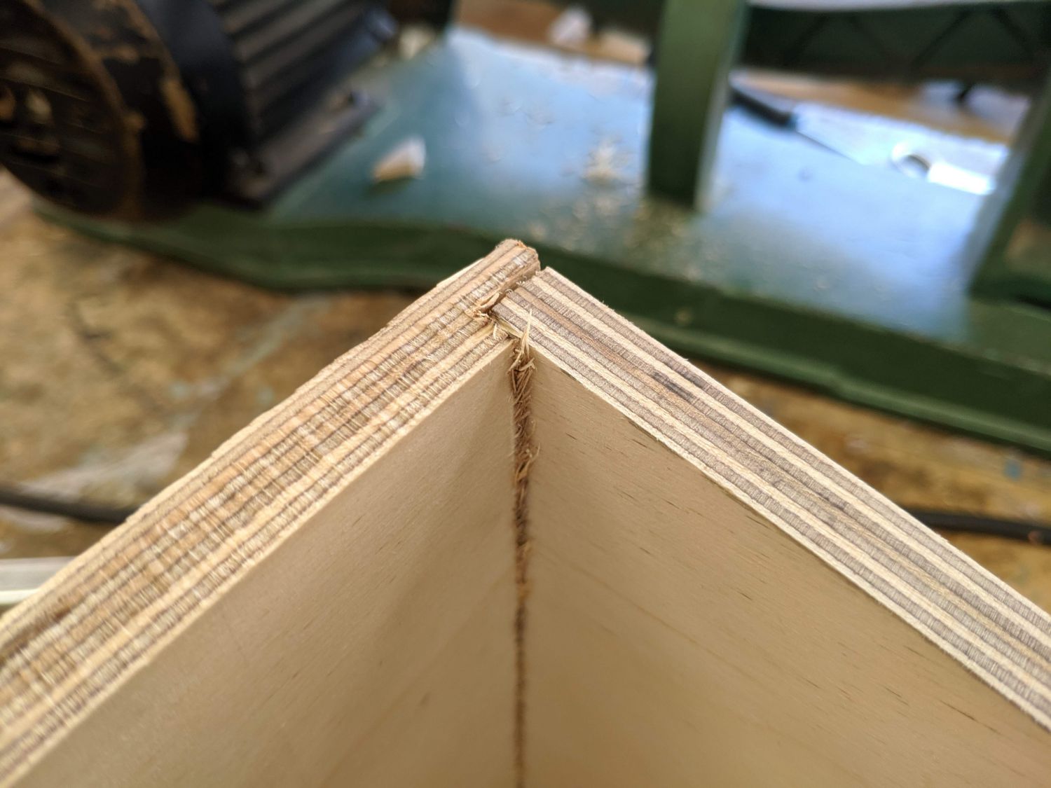
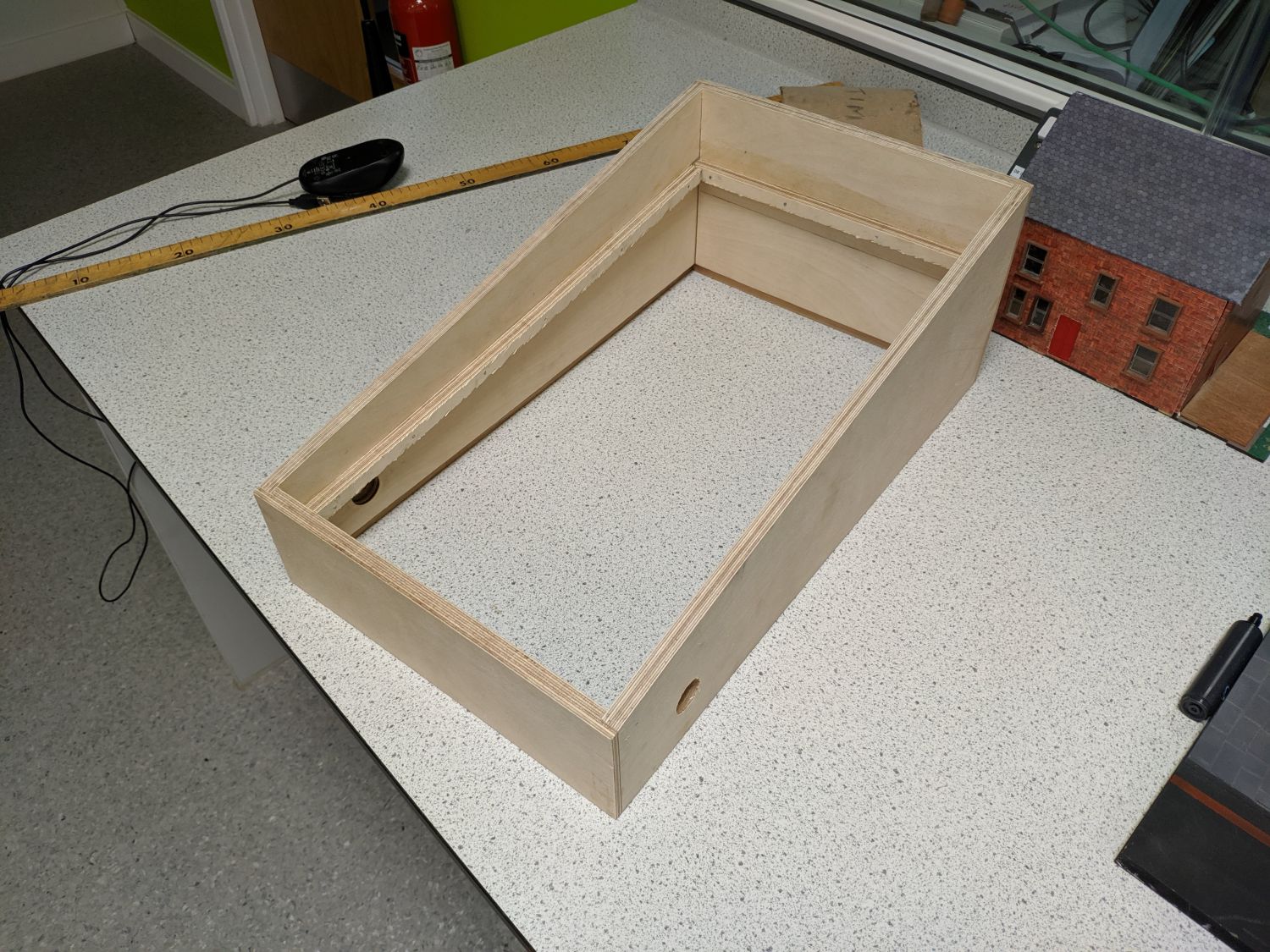
I had seen a few box designs on the internet using plywood rebate joints and knew this was how I wanted to construct the casing – once finished these are visually appealing and very strong. I picked the angle for the playfield as 7° based off commercial pinball machines.
Casing
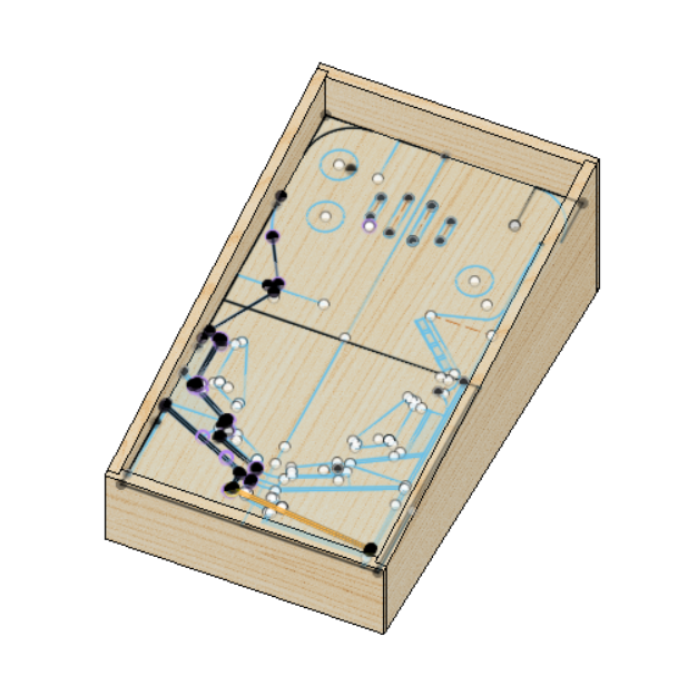
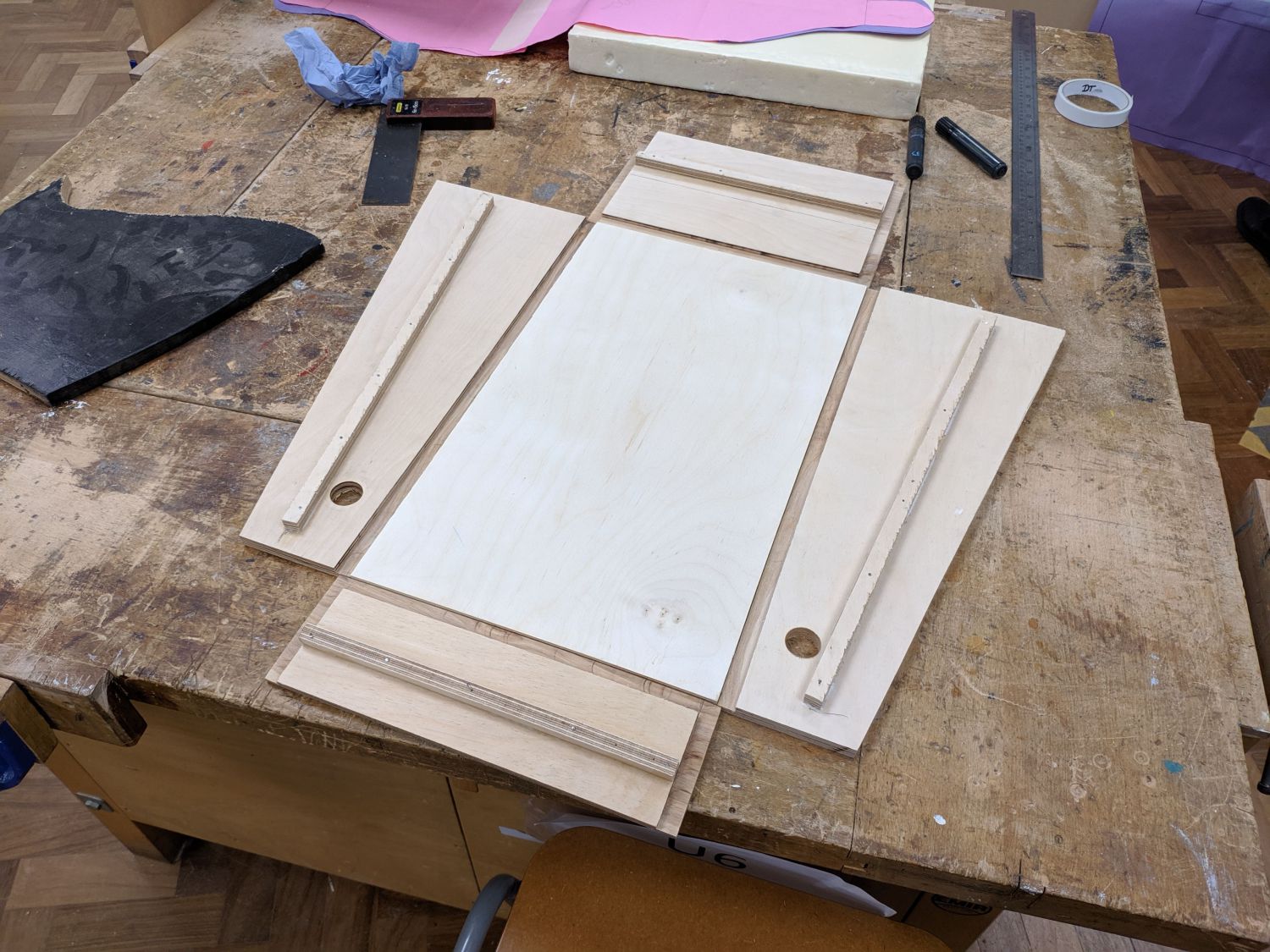
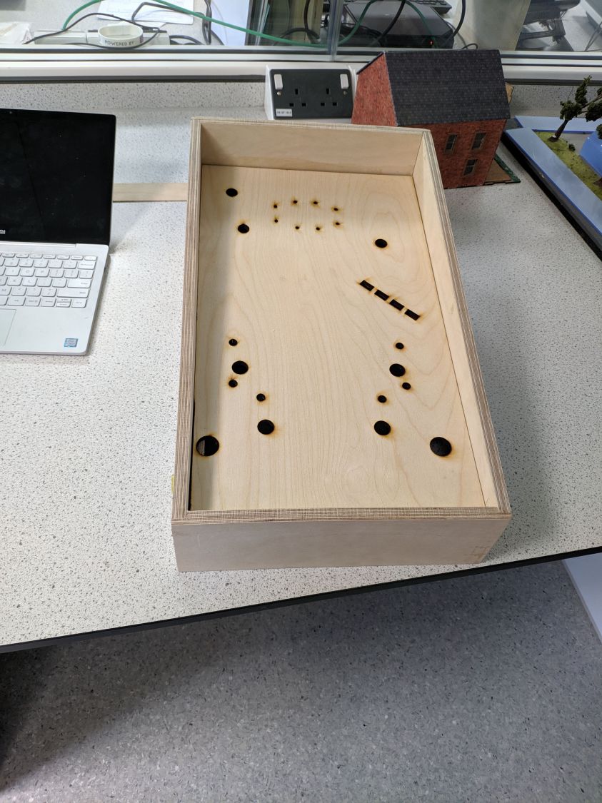
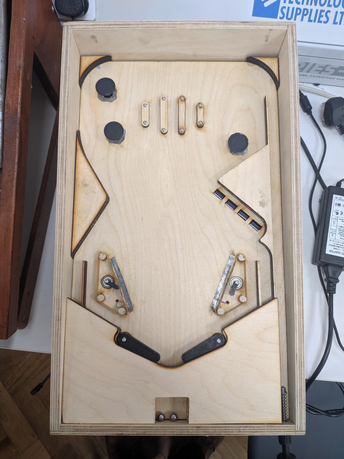
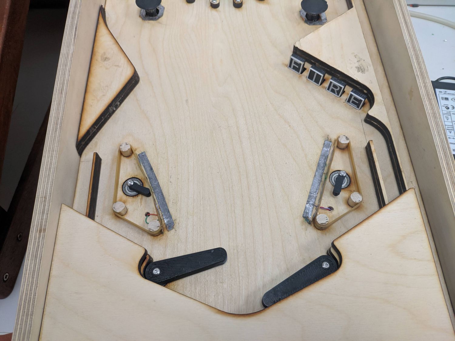
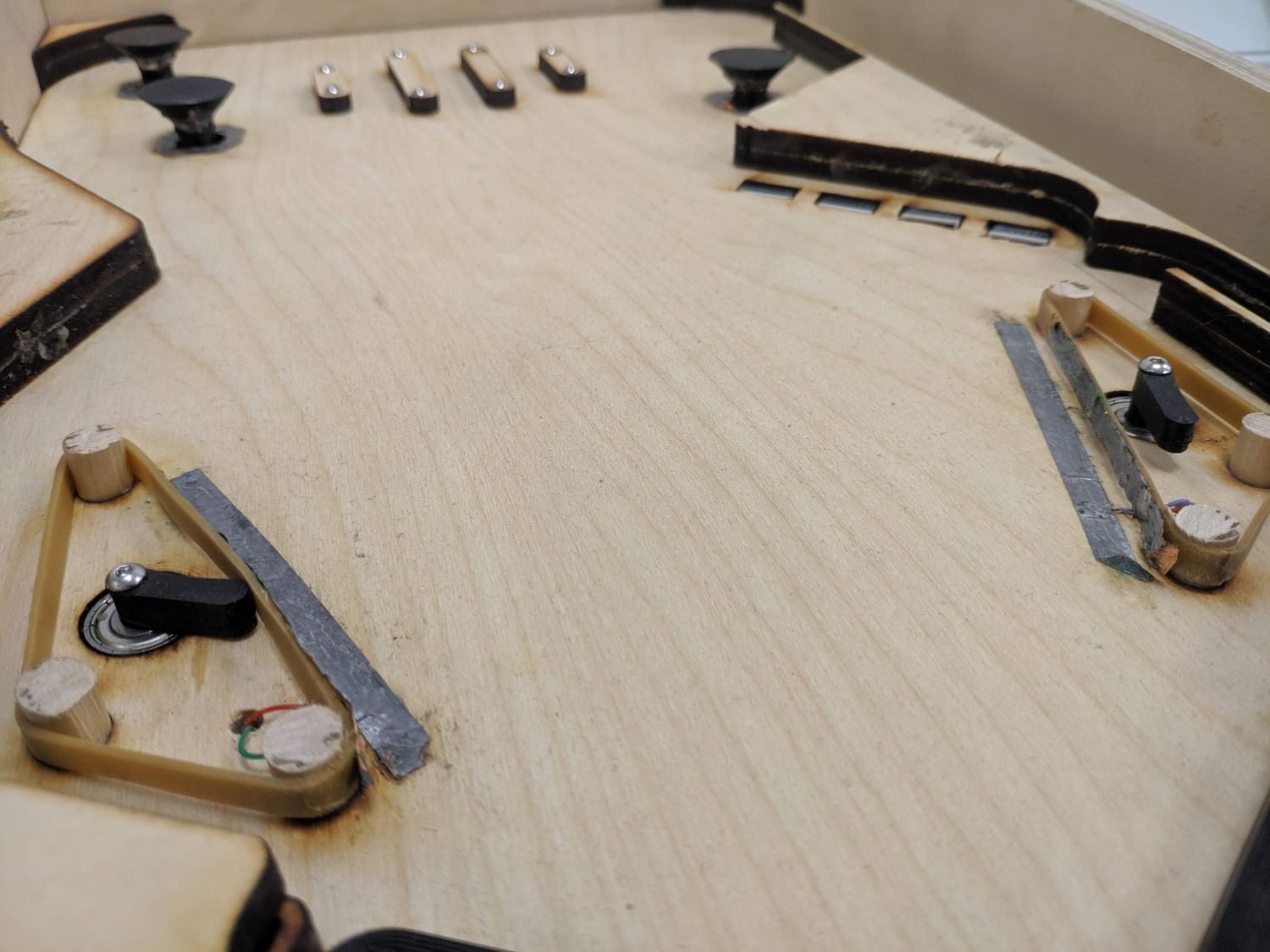
Before I started experimenting with mechanisms I knew I needed the exact dimensions of the casing to ensure I made the parts to fit. I modelled up the exact casing design in Fusion 360; this meant when it came to cutting down plywood I could simply use the dimensions given by my model. The casing is all 12mm softwood plywood – I later considered painting this but liked the exposed joints. I also designed the playfield at this point: three pop-bumpers, a set of drop targets, two slingshots, two flippers, and some interesting static parts to guide the ball around during play. The playfield is designed to lift out of the case for ease of assembly and maintenance.
All of the rebates in the plywood case were designed to be cut to a 6mm depth with a table router. All parts were initially cut down on the circular saw (apart from the sloping sides which I had to cut with a bandsaw).
Mechanism development
Now that I had the design for the case, along with the features I wanted, I decided on the full list of mechanisms to design:
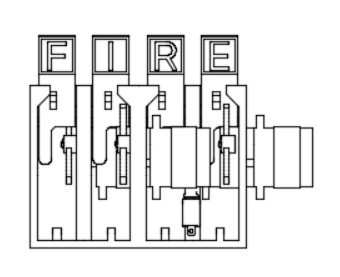
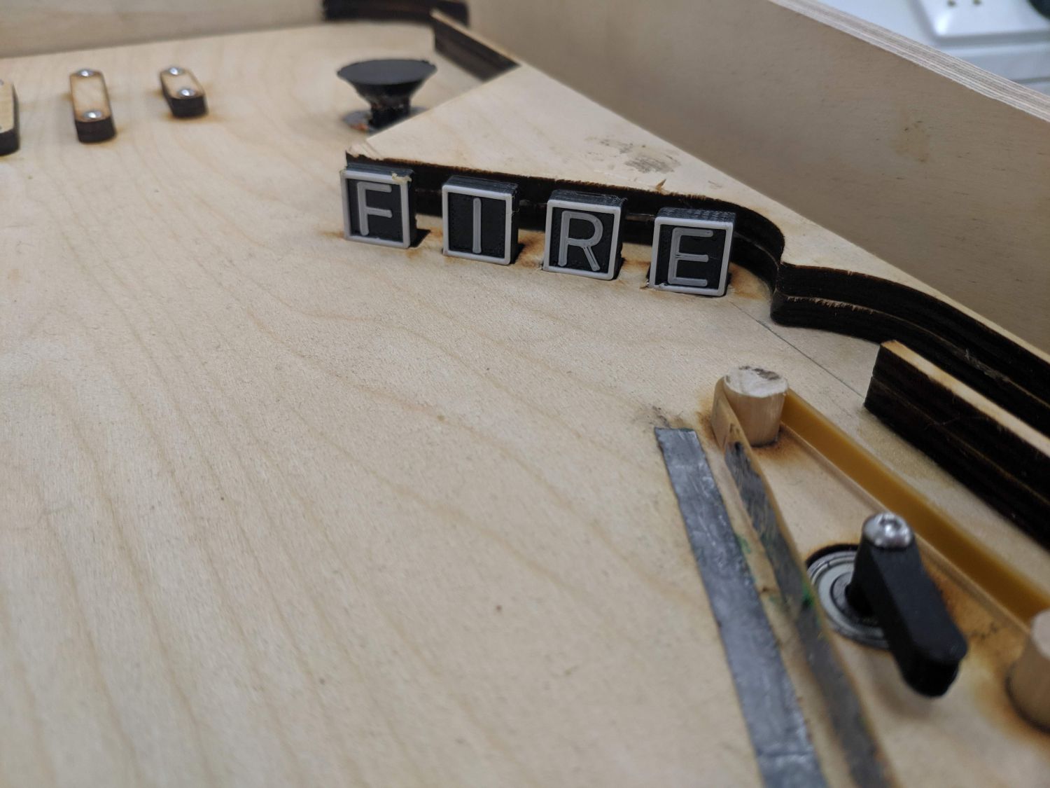
- a drop down target mechanism that could easily be stacked (i.e. multiple close to each other), would reset automatically, and could detect when the target had been knocked down.
- flippers, controlled by two buttons that activated solenoids.
- pop bumpers that, upon contact, would collapse down and push the ball away.
- slingshots that would fire the ball when contacted.
- a launching mechanism so the number of balls on the playfield could be controlled.
I did this before drawing up the full electrical plan to ensure the plan was feasible and achievable.
Drop-down targets
This was by far the most complex mechanism and I took many iterations to get a working design.
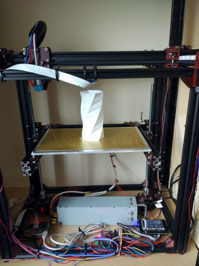
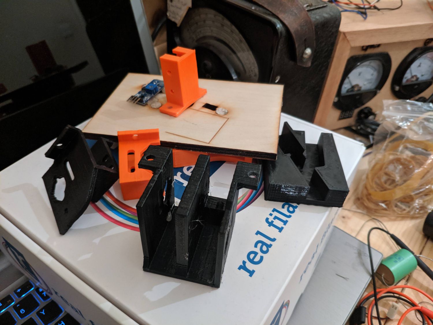
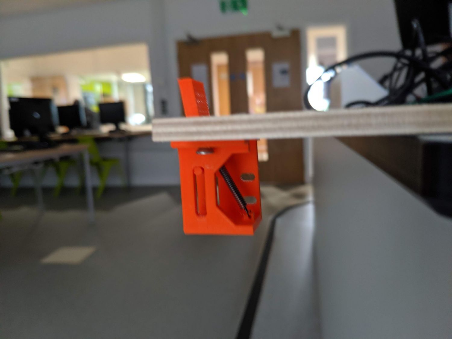
Using inspiration from an online design, I modelled a dropdown mechanism and printed it (using my self built 3D printer). The first design used a spring, tensioned so it pulled the head of the target both forward and down. This meant the target caught the top of the board, but if pushed back by a ball would quickly collapse downwards leaving the top flush with the playfield. I added the functionality for a servo to push the target back up and a microswitch to detect when it had dropped.
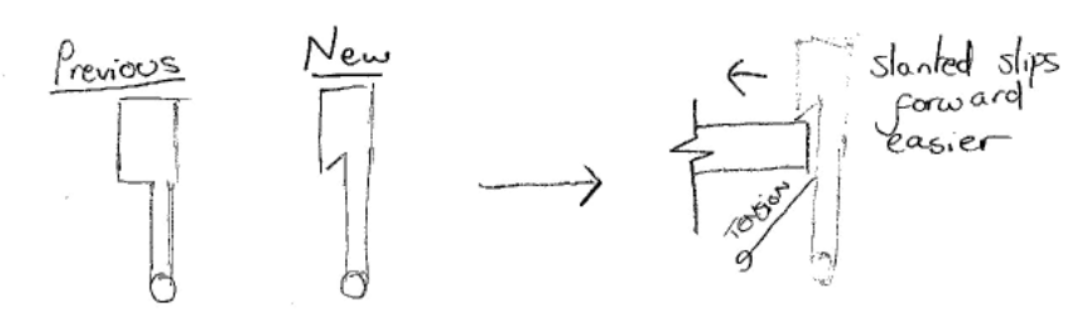
There were a number of refinements made to this design during testing. One problem I found was that the target would sometimes fail to catch onto the playfield and instead slip back down. To fix this, I added a slant to the lower ‘catch’ on the target ensuring the target would always ‘hold’ on to the board when it got pushed up.
Another issue I found was that the springs I was using to pull the targets down when pushed were pulling with too much force – this meant the servo would struggle to push it back up. I replaced all of the springs with thin rubber bands, solving this issue while leaving the mechanism functional.
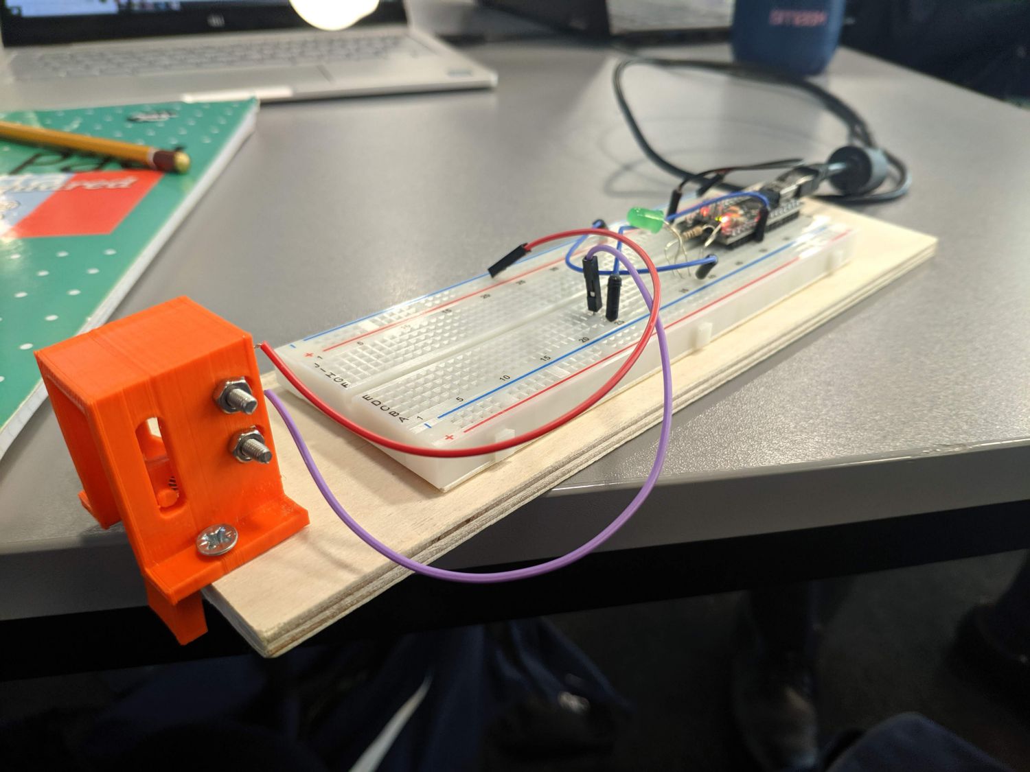
I then moved on to integrating the mechanism with the scoring system (shown in the video); when the target is dropped down a message is displayed (‘nice’) and 1000 points are added.
Unfortunately due to time constraints I had to cut the scoring system from the final product
Final component design
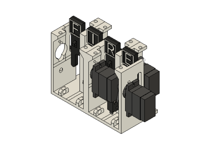
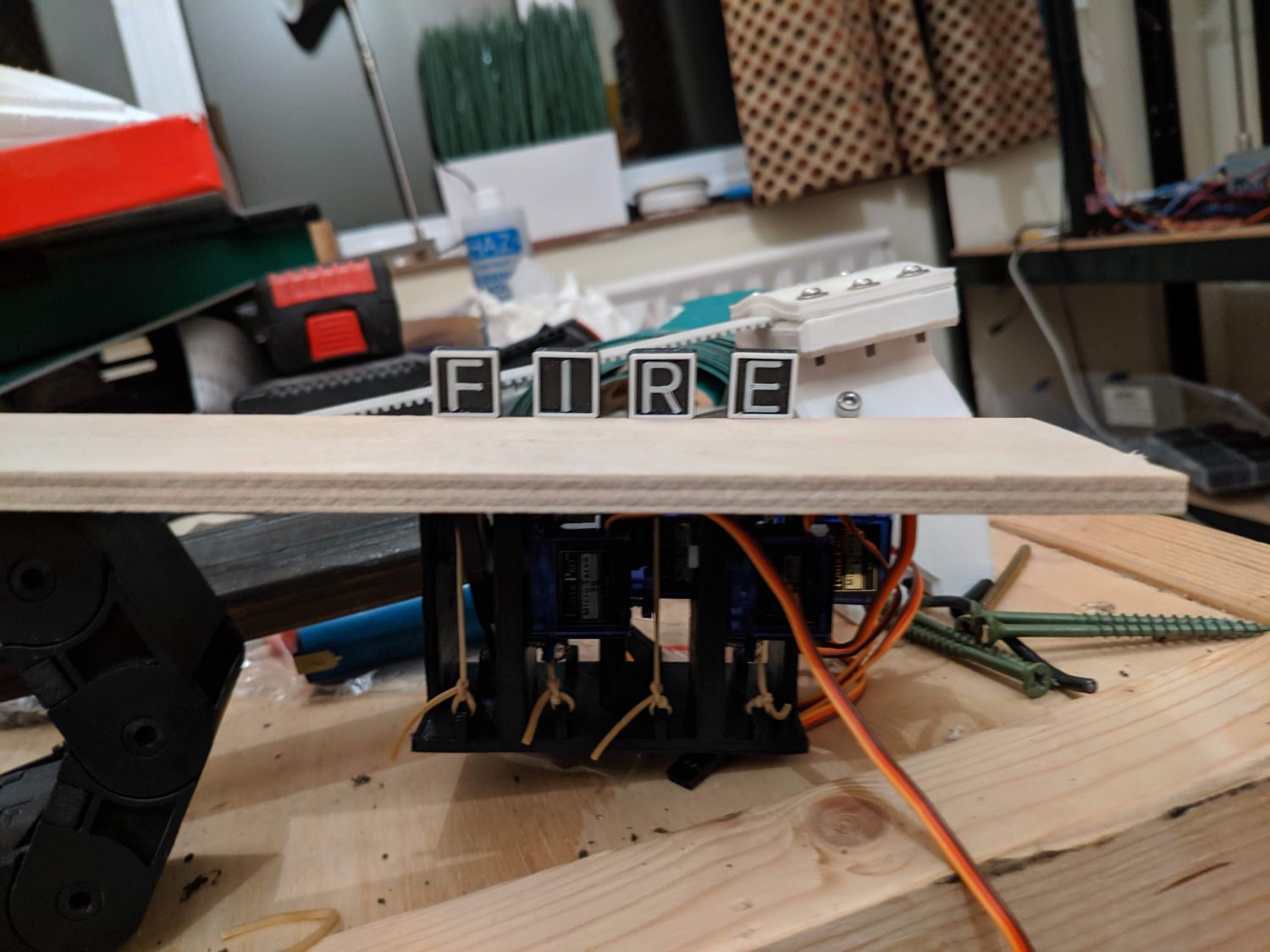
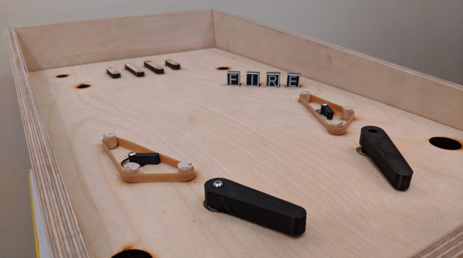
Moving from a single functioning module to a module of four dropdown targets proved challenging and took many hours of work. The primary issue was that the servos I had were too large to all be located on the same side of the module so instead had to operate on alternate sides. The tensioning elastic bands however had to remain on the same side leading to some conflicts that had to be fixed.
Eventually I was able to get the full system working by moving the microswitch location to lower down, freeing up space for the servos and elastic tensioners.
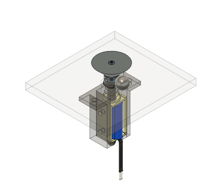
Pop bumpers
The second mechanism I prototyped was the pop bumper mechanism. This fairly simple mechanism consists of an outward angled cone that pulled down by a solenoid, projecting the ball in its proximity outwards.
In conjunction with the top piece, I designed a lower holding piece; bolts clamp the solenoid in place.

One challenge with this mechanism was the activation, i.e. how to detect when a ball is nearby. Commercial pop bumpers use a detection ring that when disturbed change the state of a switch below and trigger the bumper – this level of precision is unrealistic for such a small scale and with the facilities I have so I had to experiment with other methods.
At first I attempted to use microswitches or IR switches to detect movement when the ball came close but this did not provide the accuracy or reliability required. In the end I settled on a simple switch setup. I added a conductive ring with copper tape to both the bumper and around it on the playfield: when the ball contacts both of these pads it completes a circuit, pulling a data-line to high which can be detected by the arduino.
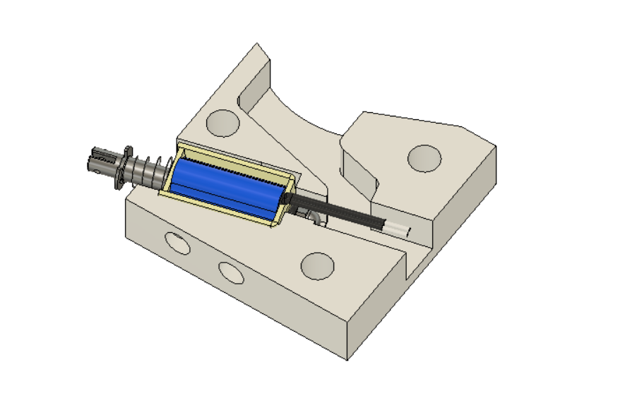
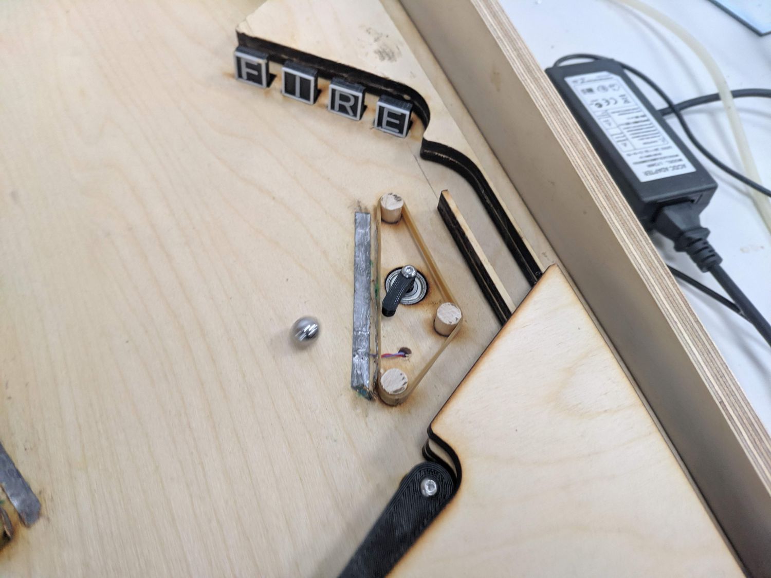
Slingshots
The slingshots, located near the bottom of the playfield can simply be passive components, with an elastic band to provide some ‘spring’ when impacted; however, I wanted to mimic full scale pinball machines by adding a response on impact.
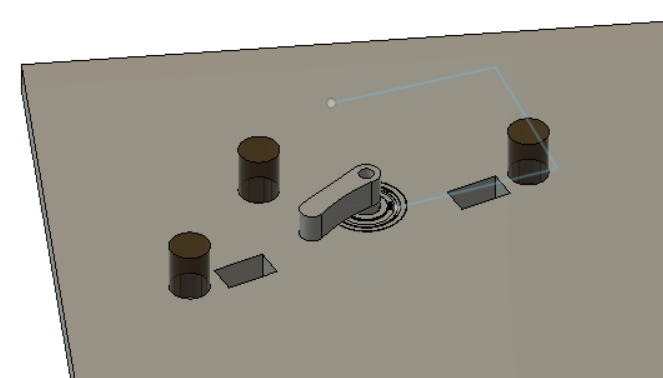
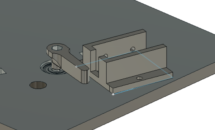
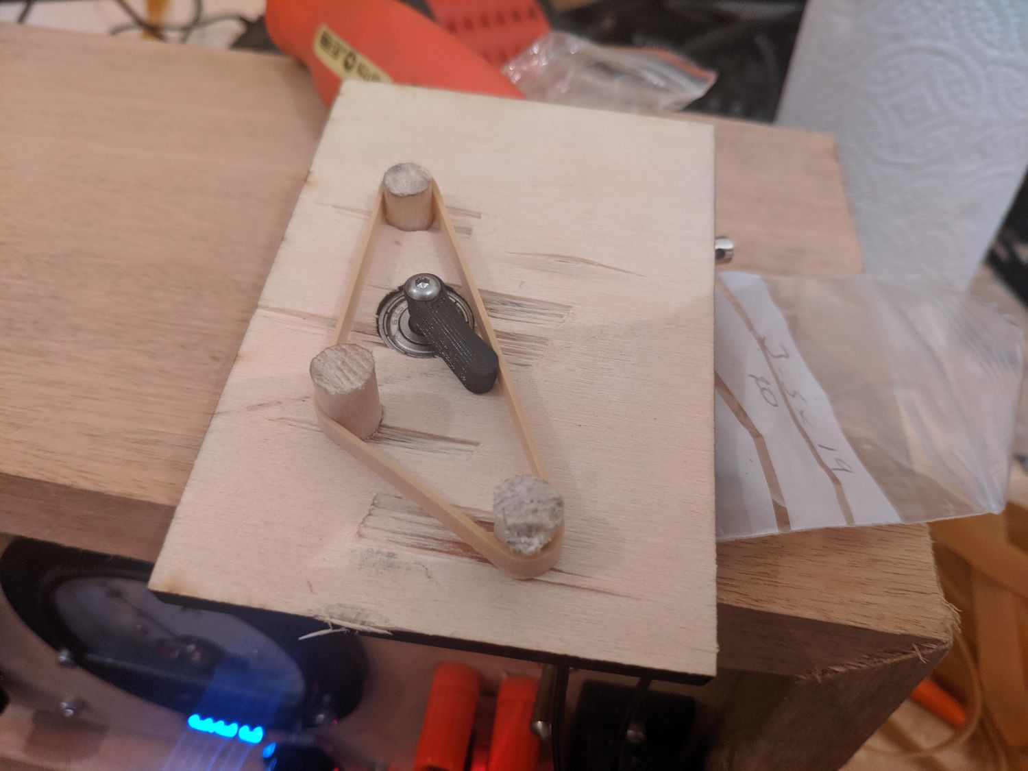
The mechanism is composed of two independent sections, the solenoid holder and the firing assembly. The firing assembly is connected through a bearing with a bolt for smooth rotational motion – the bolt locks onto a nut on the underside.
When a ball is in the proximity the slingshot is activated and fires the ball away. The left slingshot is key to hitting the drop targets.
Again the key problem with the slingshots was activation. Initially I had planned to use microswitches, which are used on full size machines, but the far smaller and lighter ball did not reliably activate them during testing. In the end I opted for a similar solution to the pop bumpers.
Flippers
The key of course to a pinball machine is the flippers! While I could have opted for a manual system, I am very glad I went for an electromechanical solution as this is one of the most functional and successful mechanisms of the project.
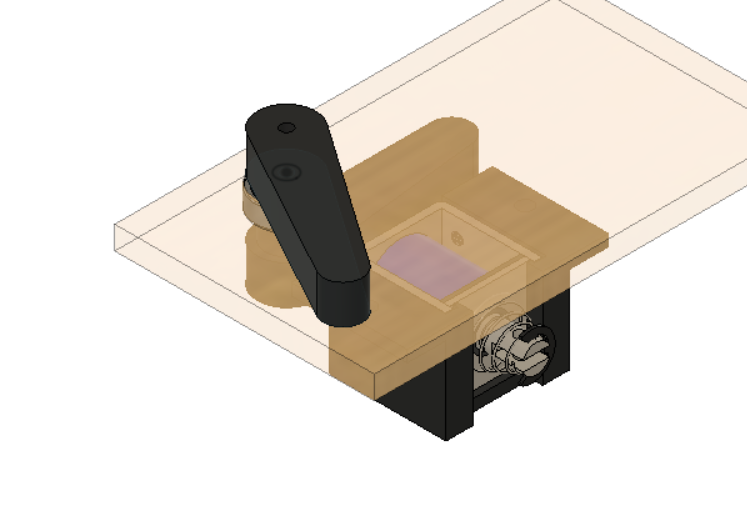
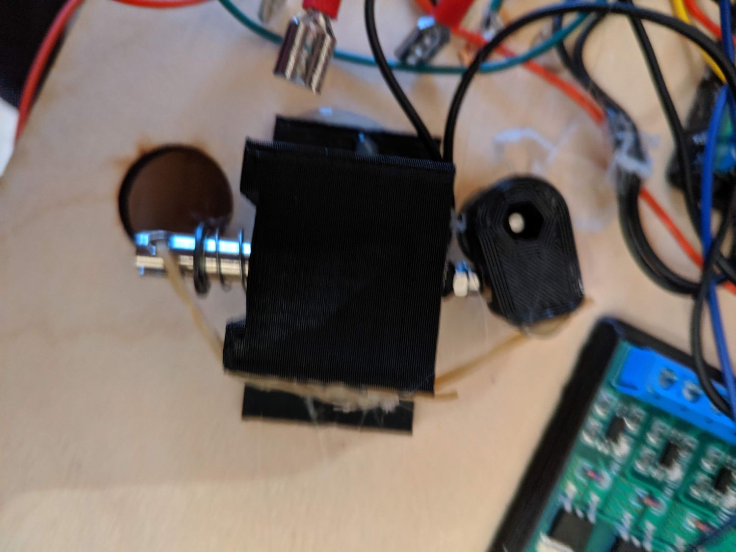
Once I started prototyping the flippers I already had a successful prototype of the slingshots so modelled the design after the slingshot firing mechanism. There are however some key differences. Because the flipper has to turn a much greater angle than the slingshot, I placed the solenoid plunger much closed to the pivot point and added a hole for magnets in the lower flipper. This way, the plunger can push the flipper to its maximum angle and then, when power is cut, return bringing the flipper with it. This did take some experimentation to get working and in the end I had to supplement it with some elastic bands as it had the tenancy to get caught.
Reload mechanism
It took multiple prototypes of the reload mechanism to get the right slope for reliable activation but eventually I was able to reliably fire a single ball at a time. Unfortunately, due to time constraints I was unable to implement this mechanism into the final product.
Manufacture and assembly
Making the case
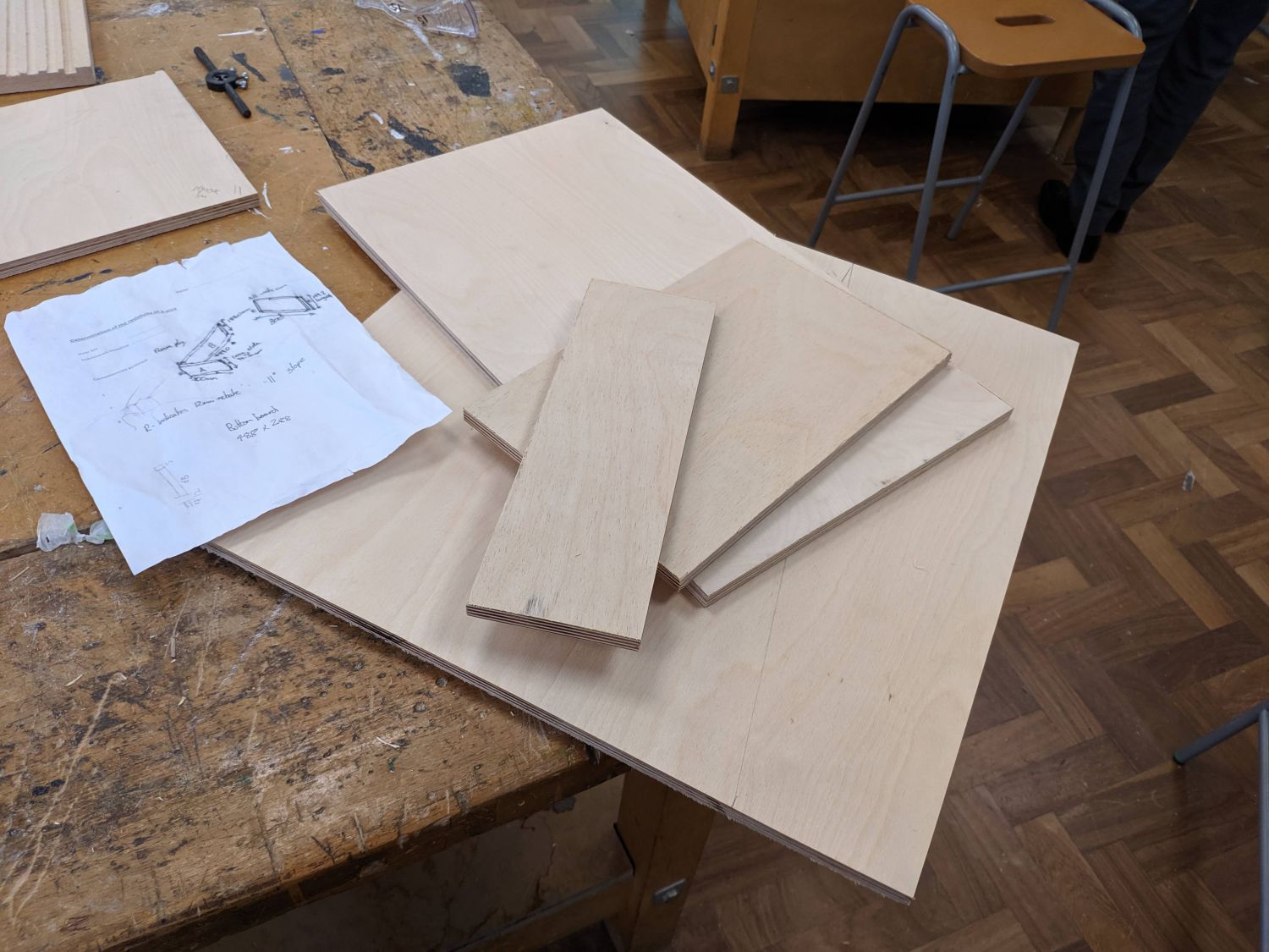
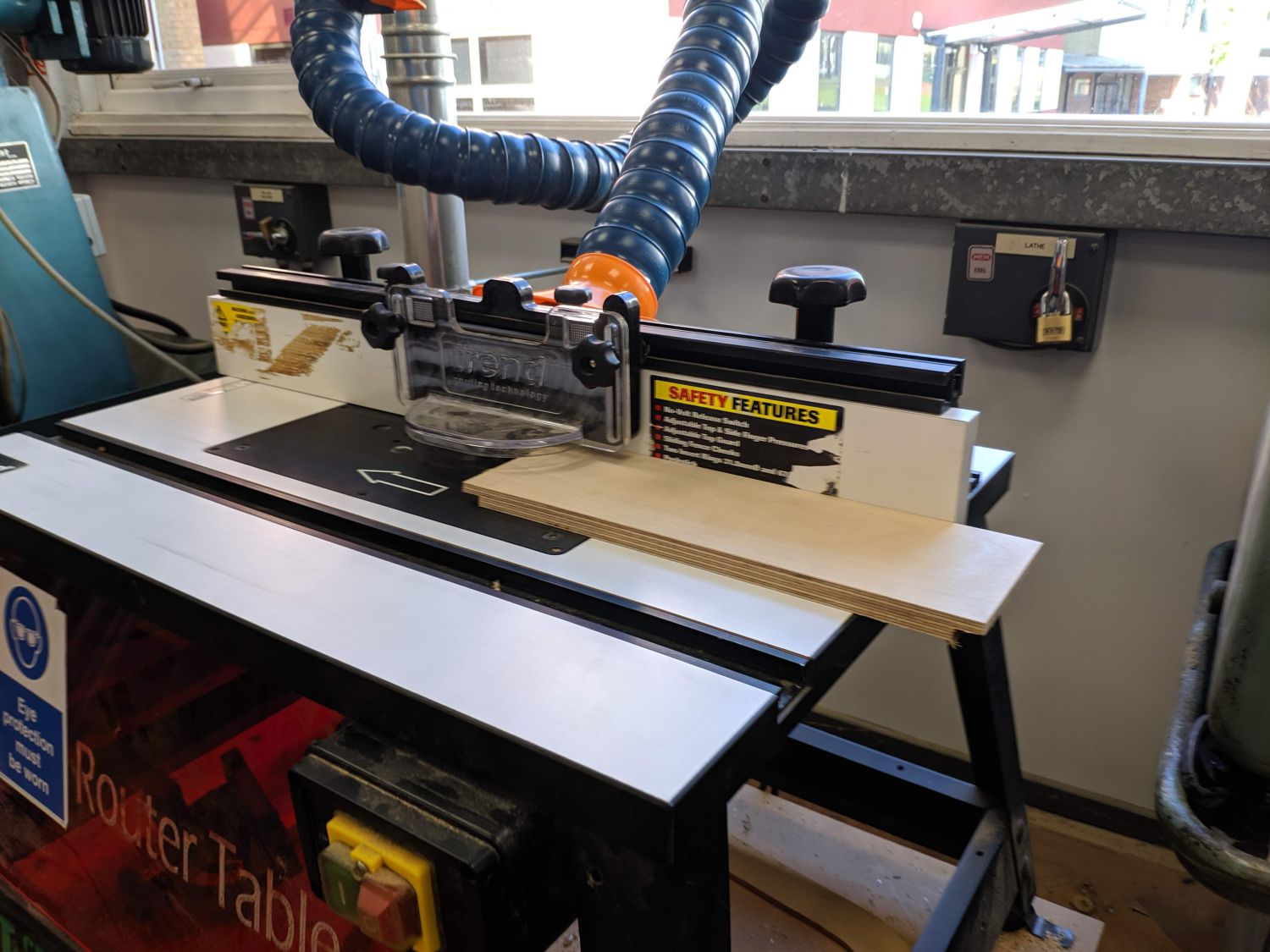
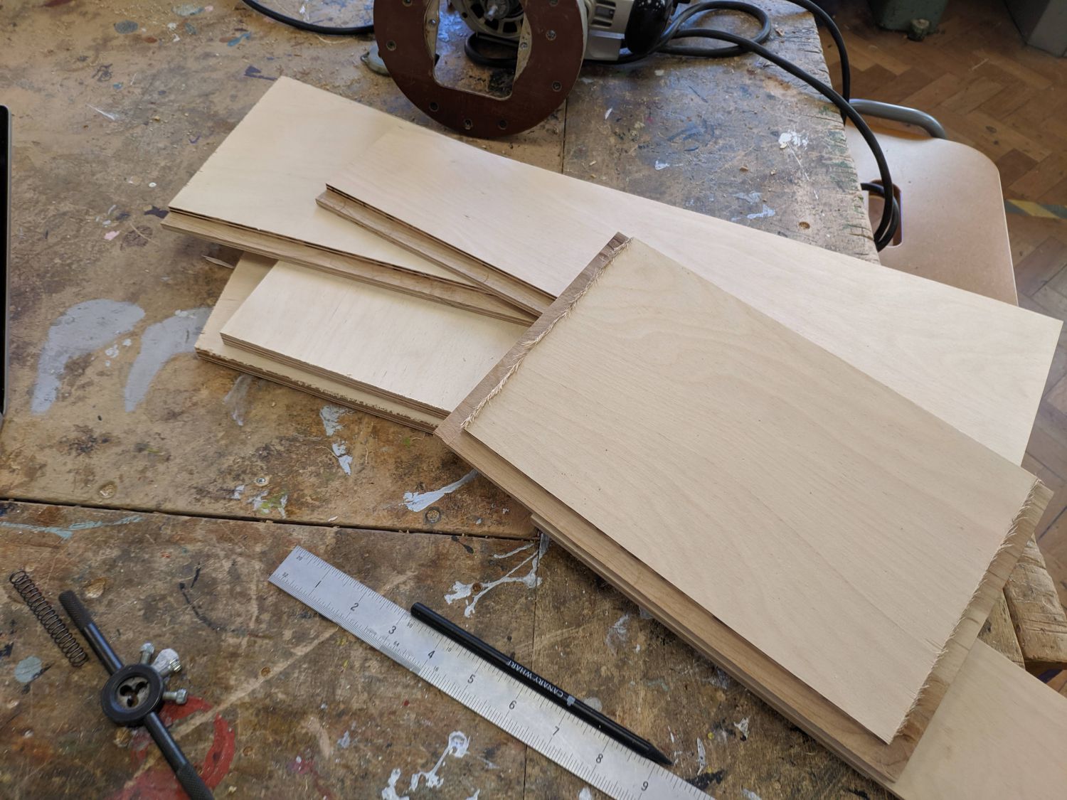
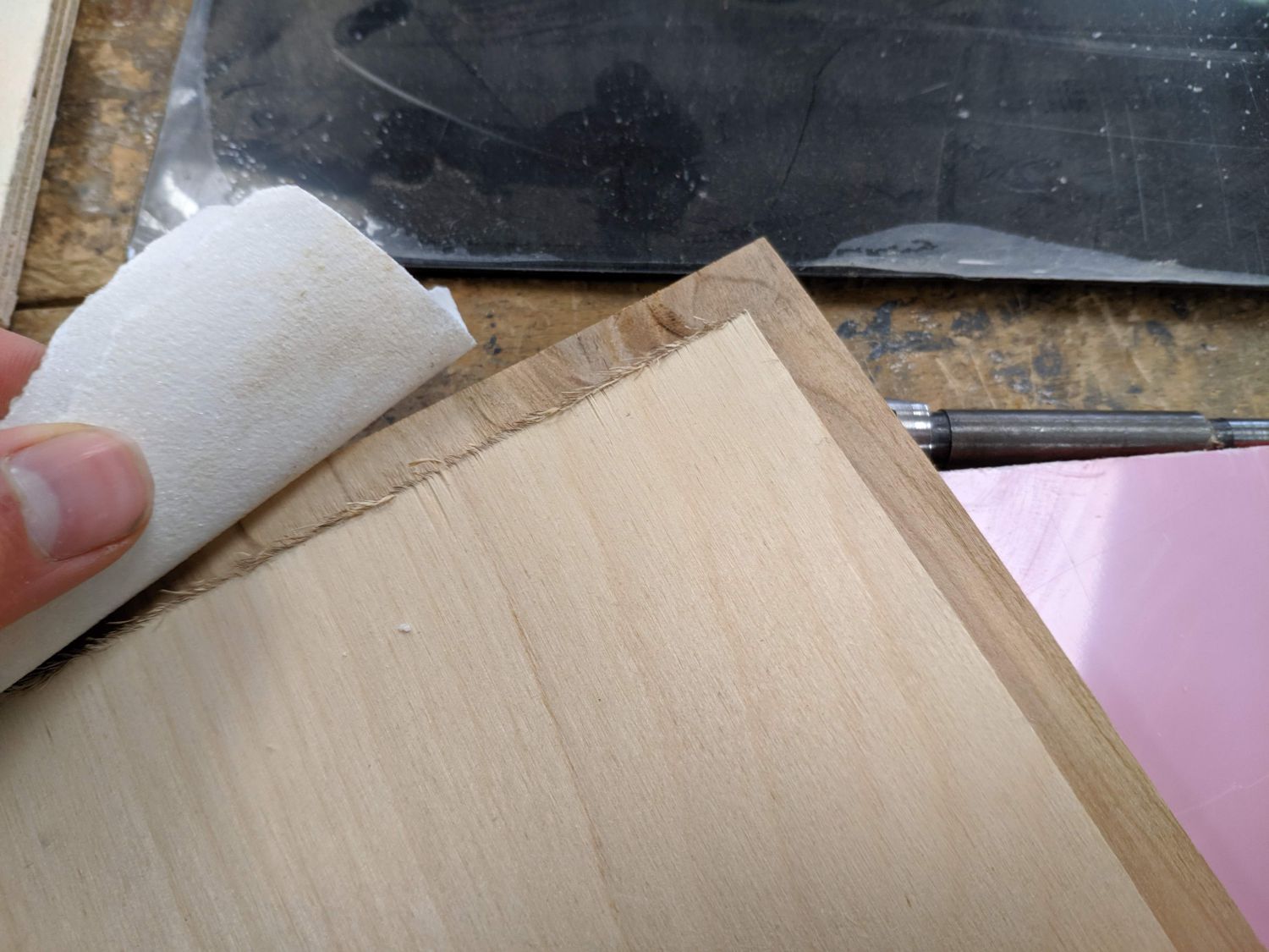
As all the designs were ready to go I simply extracted measurements from my model and began to manufacture. I had the plywood panels cut down on the circular saw (and some on the bandsaw) before setting up the table router to cut rebates in the plywood. After calibration with some scrap, I was able to do the operation in a single pass. I then removed the loose fibres with some high-grit sandpaper and test-fitted the joints.
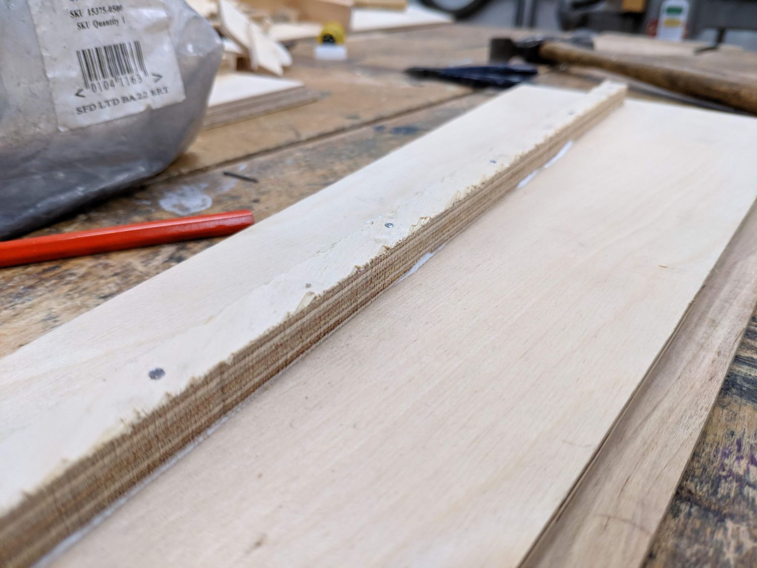
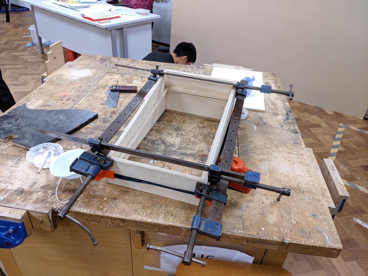
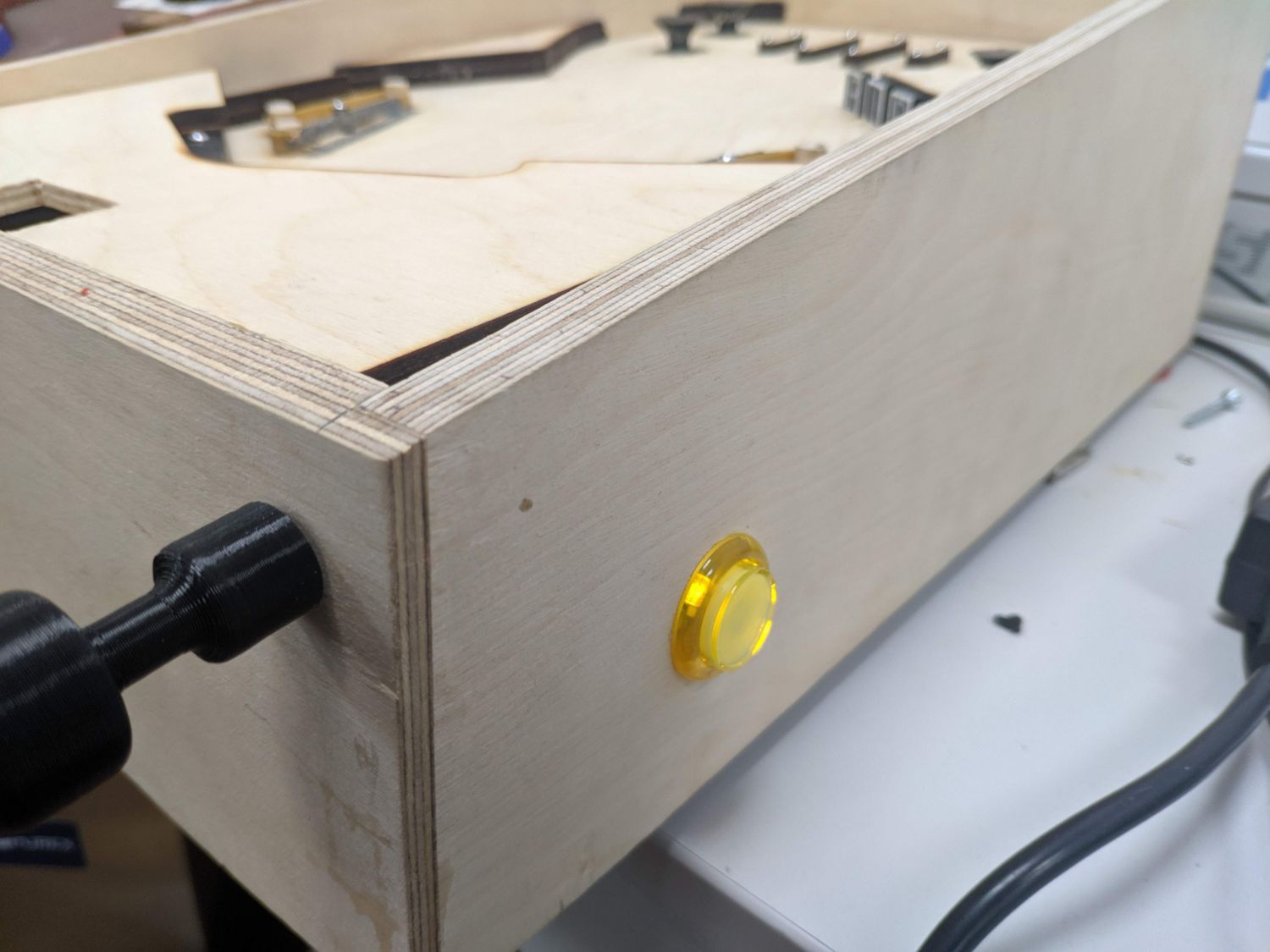
Once I had confirmed all the parts would fit together nicely, I drilled the holes for the buttons in each side. I then used panel pins and glue to attach the playfield holder all around the case. Once all the parts were ready I glued and clamped the case together – by using a picture frame ratchet strap first with 90° corners I ensured the case was square. I double checked the square by measuring each diagonal at the bottom before adding extra clamps.
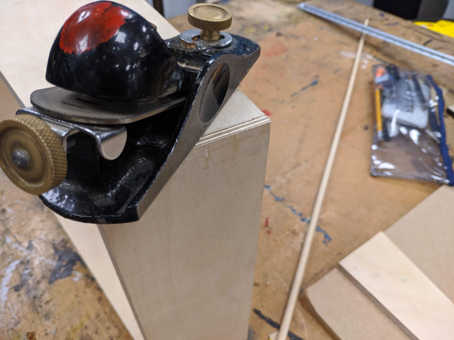
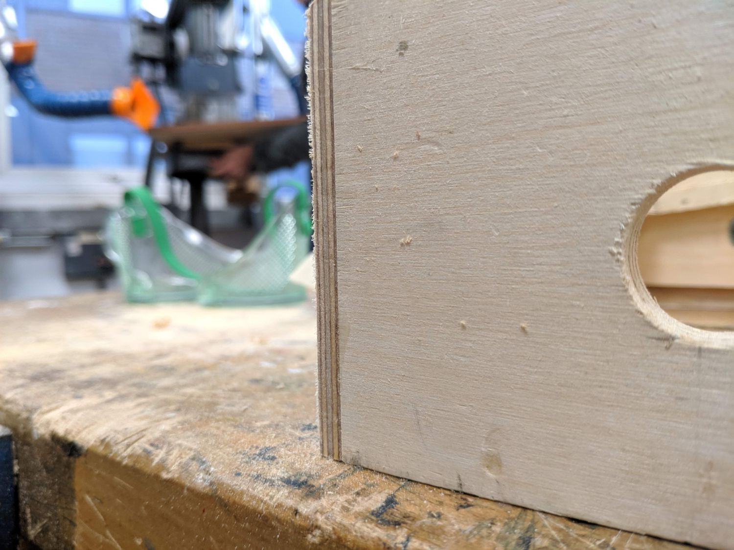
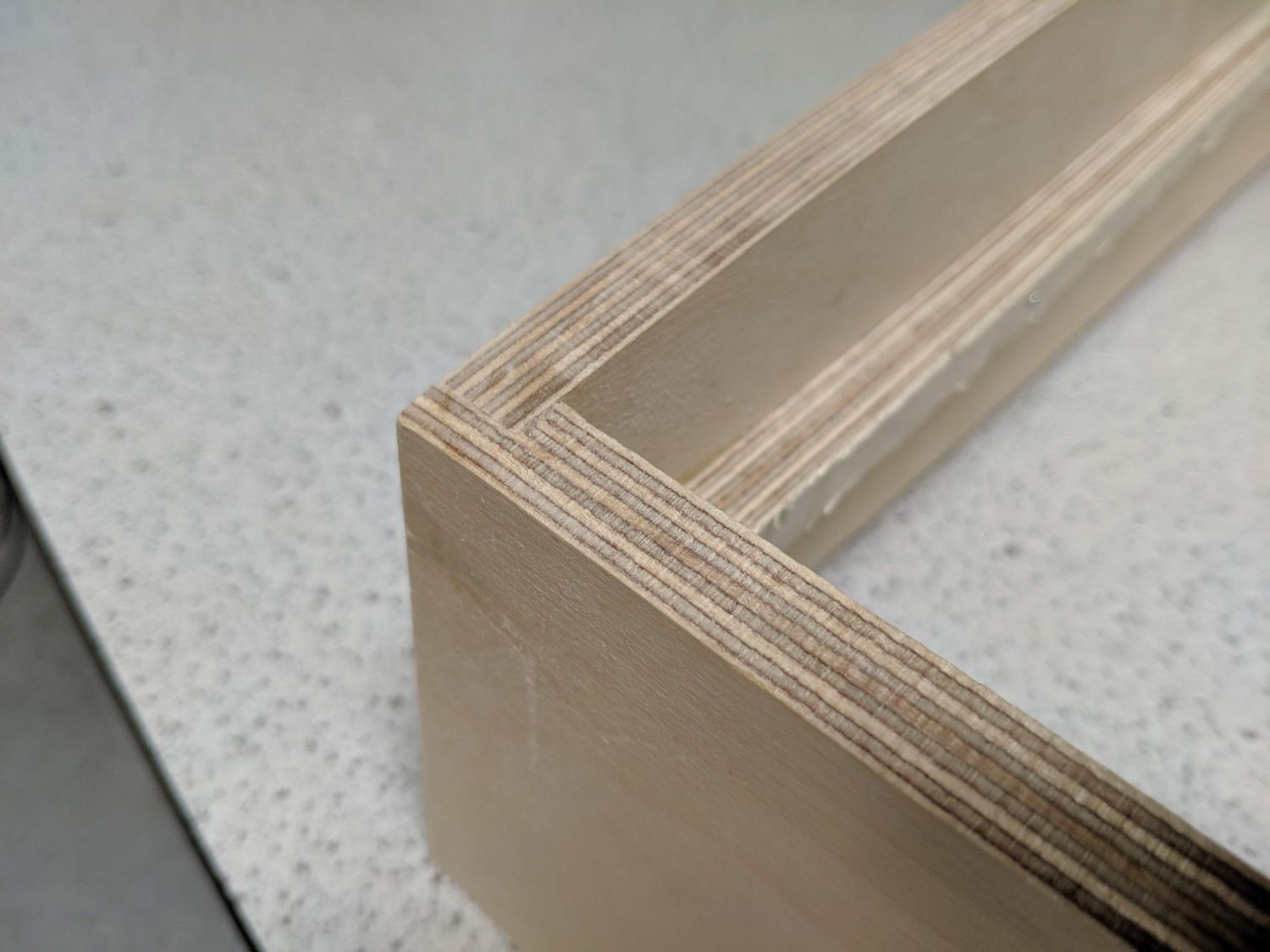
While the gluing was not perfect, with a little hand planing the joints were finished to a smooth transition and look great! The rebate joints are incredibly strong and after laser cutting my base plate and lowering it in, the pinball machine is even less prone to deformation.
Electronics and final assembly
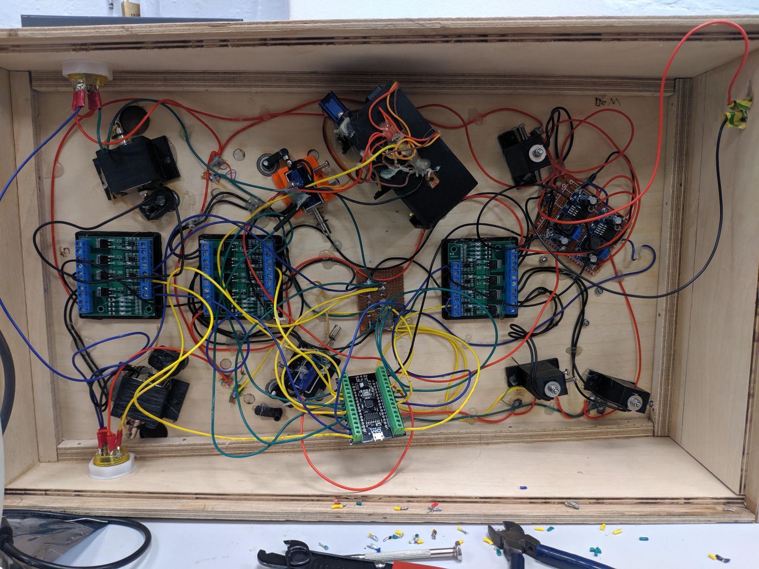
All that was left was to assemble all of the components into one board and wire them together. I started by fixing all the mechanisms to the board and confirmed once again that they worked as intended. I then started on the wiring.
Each input in the project is essentially a switch. When a flipper button is pressed, or when a ball closes a pop-bumper circuit, the signal line coming out of that switch is powered and this change can be read by the microcontroller. All of the signal lines are pulled to ground with a high value resistor so when the circuit is not closed, they are not floating. One 5V power line runs in a ring around the pinball playfield connecting to one side of the normally closed switches.
The outputs of the microcontroller can only provide 40mA, this is far too little for the solenoids so I used simple MOSFET boards to connect and disconnect the solenoids from the power supply. There are two power supplies on board, one providing a variable voltage to the flipper solenoids, allowing power adjustment, and another providing the logic voltage (5V). Most of the flippers are connected to the 24V external power supply which connects into the pinball case with an aluminium surface mount DC jack.
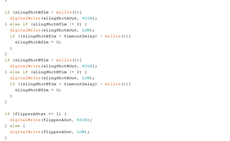
I then used the arduino IDE to put together a sketch that reacted to inputs with outputs. One problem I faced was that if a bumper was activated or a slingshot fired they could get caught in a negative feedback loop and be stuck on. This could eventually lead to the solenoid burning out. I fixed this by adding a timeout for each.
Following a minor disaster due to incorrect servo wiring which burned out the MCU, I replaced the board and ensured the problem was fixed.
Once I had confirmed the functionality of the whole board, I permanently wood glued all of the static features, using superglue as a temporary fixing.
Reflection and improvements
In the end I there were a number of things I was unable to implement within the time limit. These included the scoring system (prototype shown in video previously) along with the electromechanical reloading mechanism. I also would have liked to paint the playfield with the original design calling for a night sky theme, however the exposed plywood joints and surfaces do have some aesthetic appeal.
Shown right is a video demonstrating the working functionality of the pinball machine. You can see the pop-bumper and slingshot detection method working, though will some modifications they could perhaps be more sensitive.
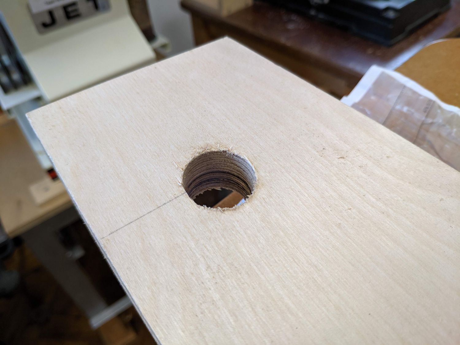
Instead of the auto-reload system, I cut a hole in the top cover of the pinball machine with the bandsaw and used some scraps to ensure all balls were guided to this point – this works well and also provides a place to store the balls when the machine is not in use.
Overall I am very happy with how it turned out and feel the electrical elements really add to the gameplay.