
Over the past few months I’ve been designing quite a few PCBs and have been interested in ways to speed up assembly.
In industrial manufacturing, solder paste is used to completely automate the soldering process of surface mounted components. Solder paste is dispensed onto the pads of the circuit board and components are then placed on the board with a Pick and Place machine. Finally, the board enters an oven, all of the solder paste ‘reflows’, and all of the components are pulled into alignment.
For my small scale uses (only 1/2 boards needed per design) a pick and place machine might be a bit overkill, but a reflow oven could reduce assembly times significantly. Stencils can be purchased from PCB manufacturers which makes depositing an even layer of solder paste on all pads simple. Then components can just be placed on the board and the solder reflowed.

Inspired by maker.moekoe’s project, I decided to recycle an old steam iron to make a hot plate that reflows SMT boards for speedy assembly and incredibly neat solder joints.

This post will only cover the the controller board, with the chassis assembly and integration detailed in an upcoming post.
Circuit design
Microcontroller Unit (MCU)
For this project, I wanted to implement an STM32 microcontroller, which are widely availible and well documented. I decided the the board needed to be able to:
- read data from an SPI thermocouple interface IC
- switch a solid-state relay to control the hot plate temperature
- drive an SPI OLED display to provide a user interface
- interface with an external rotary encoder for interface navigation
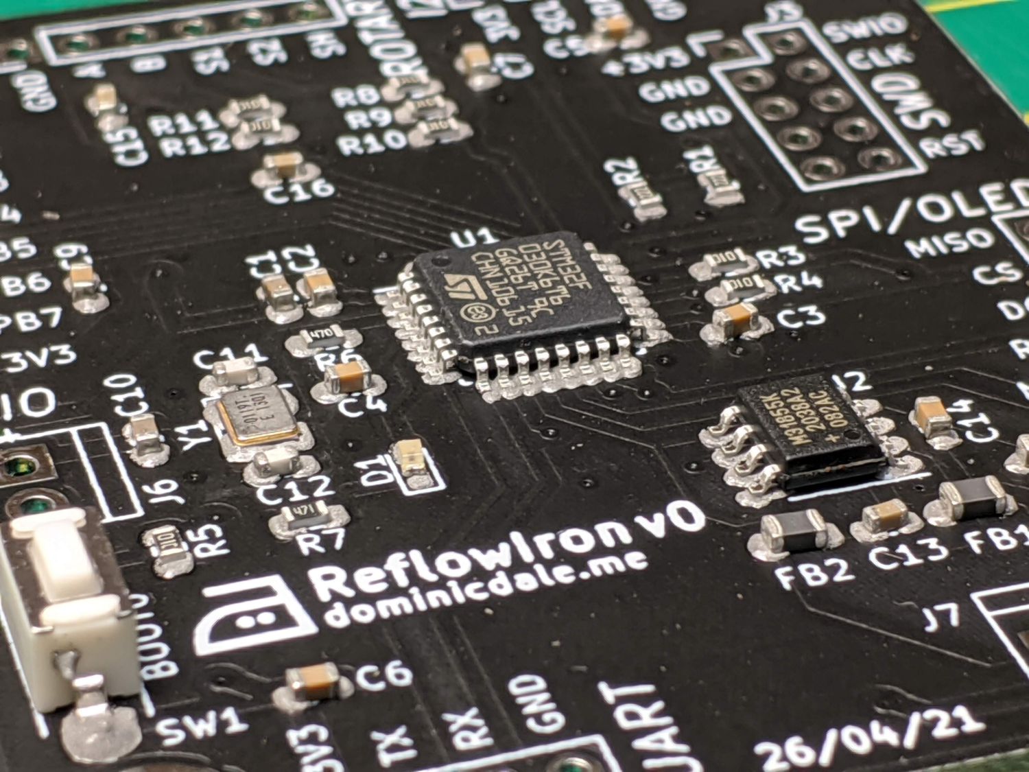
From these requirements I was able to pick a suitable MCU, the STM32F030K6. This has sufficient I/O pins and flash storage for my purposes.
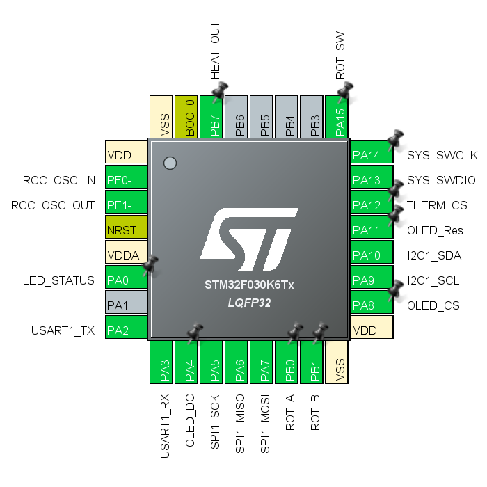
With my MCU decided, I loaded it into STM32CubeMX, an ST program which allows for graphical chip configuration; I then designated pins for each device. The benefit of doing this before designing the schematic is that you can group pins going to the same physical areas together and CubeMX will identify any conflicts with the layout. I went back multiple times during the design process to make changes to the pinout as physical layout demanded.
Schematic
This was the first major project I used KiCAD for, so while desining the schematic I was also getting used to the new software. I much prefer the KiCAD built-in libraries which seem far less cluttered than those in Eagle.
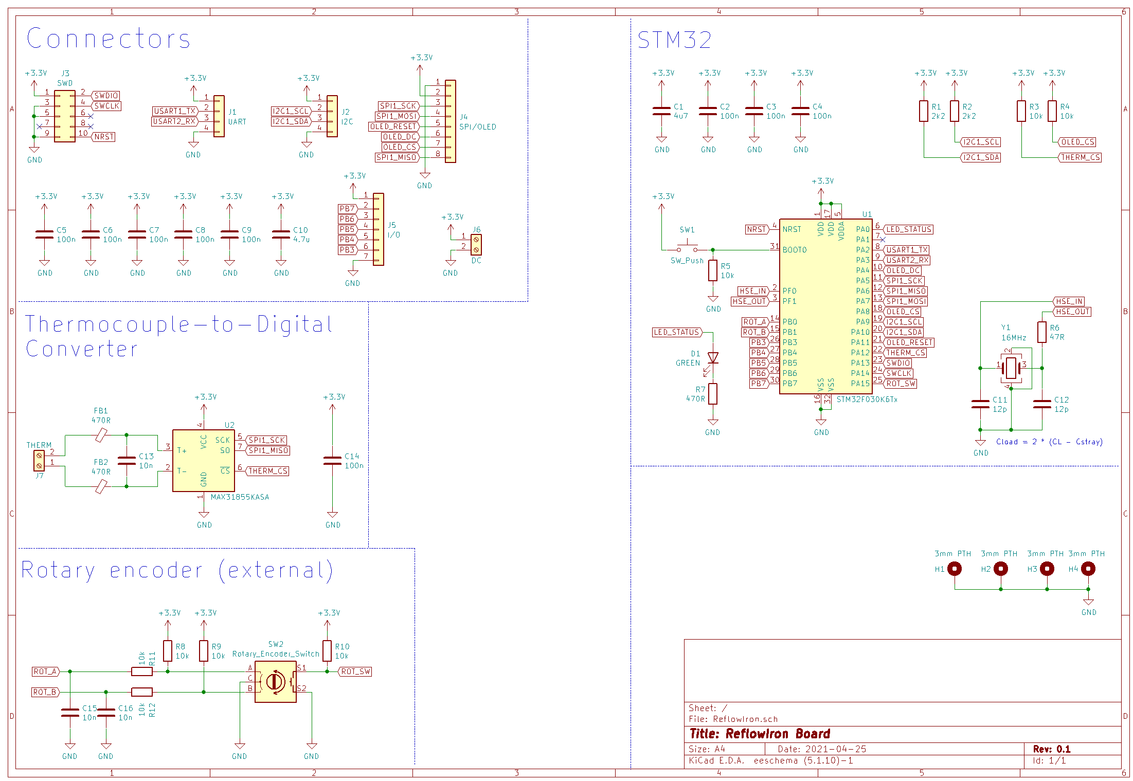
I tried to use best practice when connecting everything such as placing capacitors near every connector and IC power input. The schematic is grouped into different functional areas.
MCU and external crystal
The MCU requires minimal external conponents to function. I connected a crystal clock, but in reality, the internal RC oscillator would likely have been sufficient for my purposes. Decoupling capacitors at all power inputs were also included.
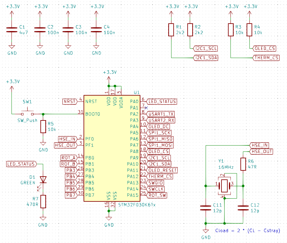
I added breakouts for all unused MCU pins for maximum flexibility.
Rotary encoder
The rotary encoder is the key interface for the hot plate controller. In this case the encoder needed to be able to control directional scrolling through menus and entrance into submenus; an incremental encoder was chosen.
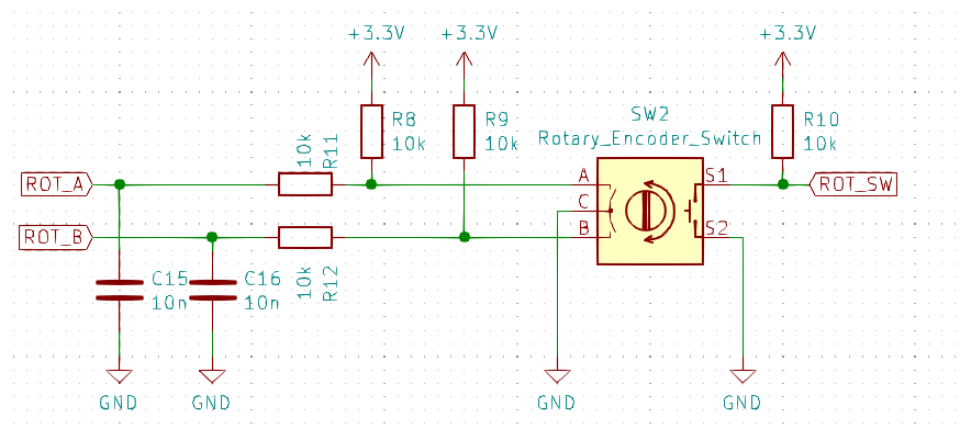
Incremental encoders have two outputs, A and B, which turn on and off with the rotation of the shaft. As demonstrated in the adjacent animation, the direction of rotation can be determined based on the input sequence. Often an additional input used an index, which goes high when the encoder is at its ‘zero’ position: for our application this is less important.
The button for the encoder simply pulls a digital input low when pressed – digital debouncing takes place in software.
Thermocouple circuitry
While I could have used a thermistor, a thermoucouple is only marginally more expensive and gives far more accurate temperature readings. I used a K-type thermocouple in a metal threaded casing to screw directly into the base of the iron.
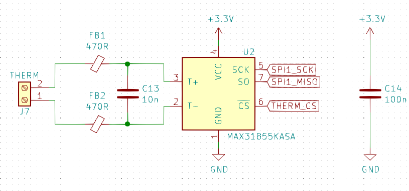
The MAX31855 is a thermocouple interface that converts the small analouge signal from the thermocouple to a digital SPI output. Ferrite beads on the thermocouple input suppress high frequency noise.
PCB layout
With the schematic complete I could move onto placing physical components. To minimise I kept this design two-layer. Given the premise of the project, I wanted it to be small and use SMT components where practical.
I started with the MCU at the centre then added the crystal and other components that needed to be physically closest to it. After the rest of the footprints were roughly in place I defined the board outline and arranged the headers so they were all easily accessible.
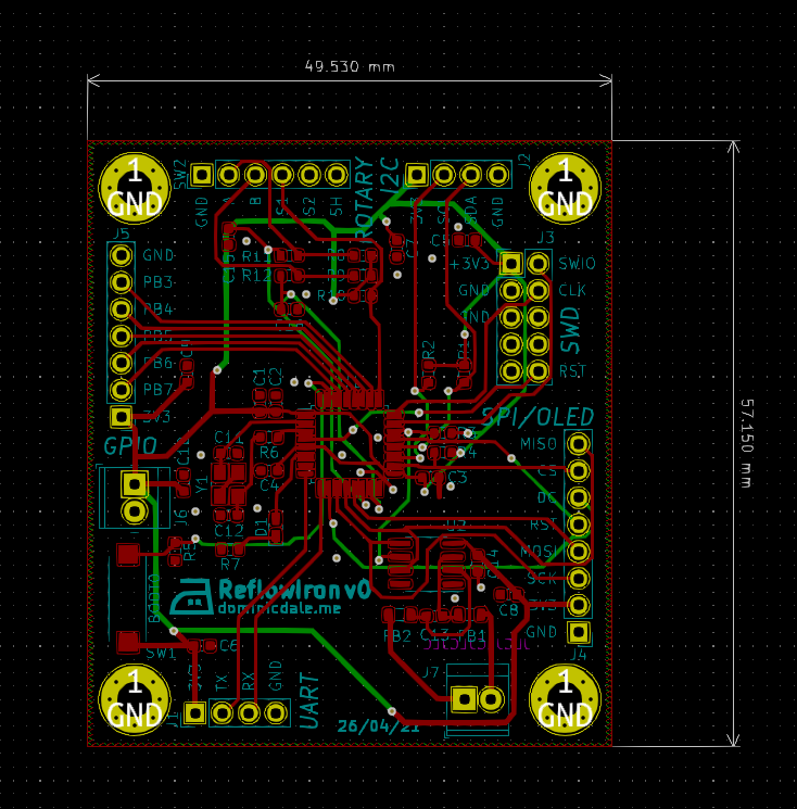
Both sides of the board include ground fills in areas without signal or power traces; this means I didn’t need to worry about routing ground lines to any components. Traces were sized according to current carrying capacity though in reality all were overspecified as there was sufficient space.
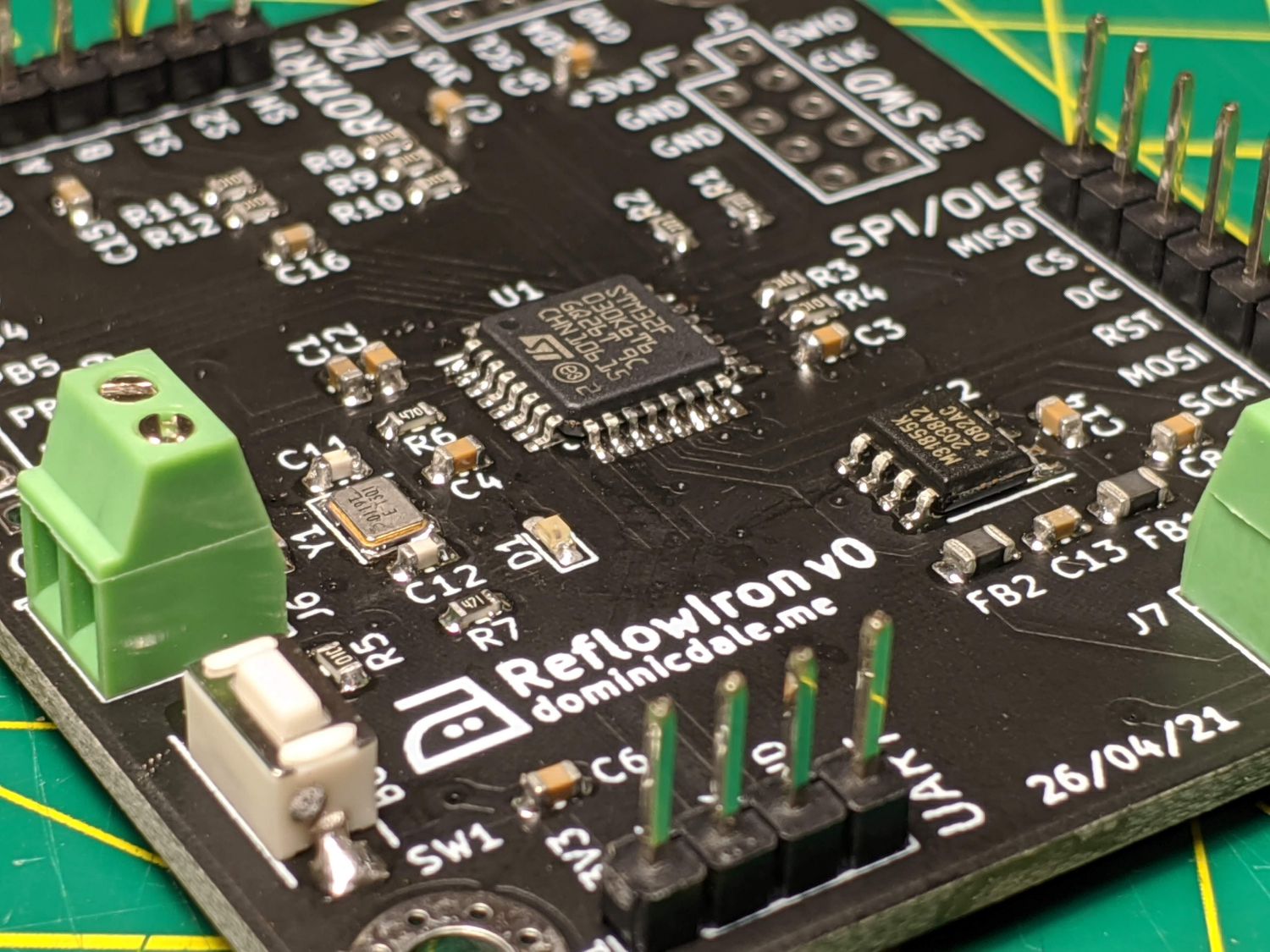
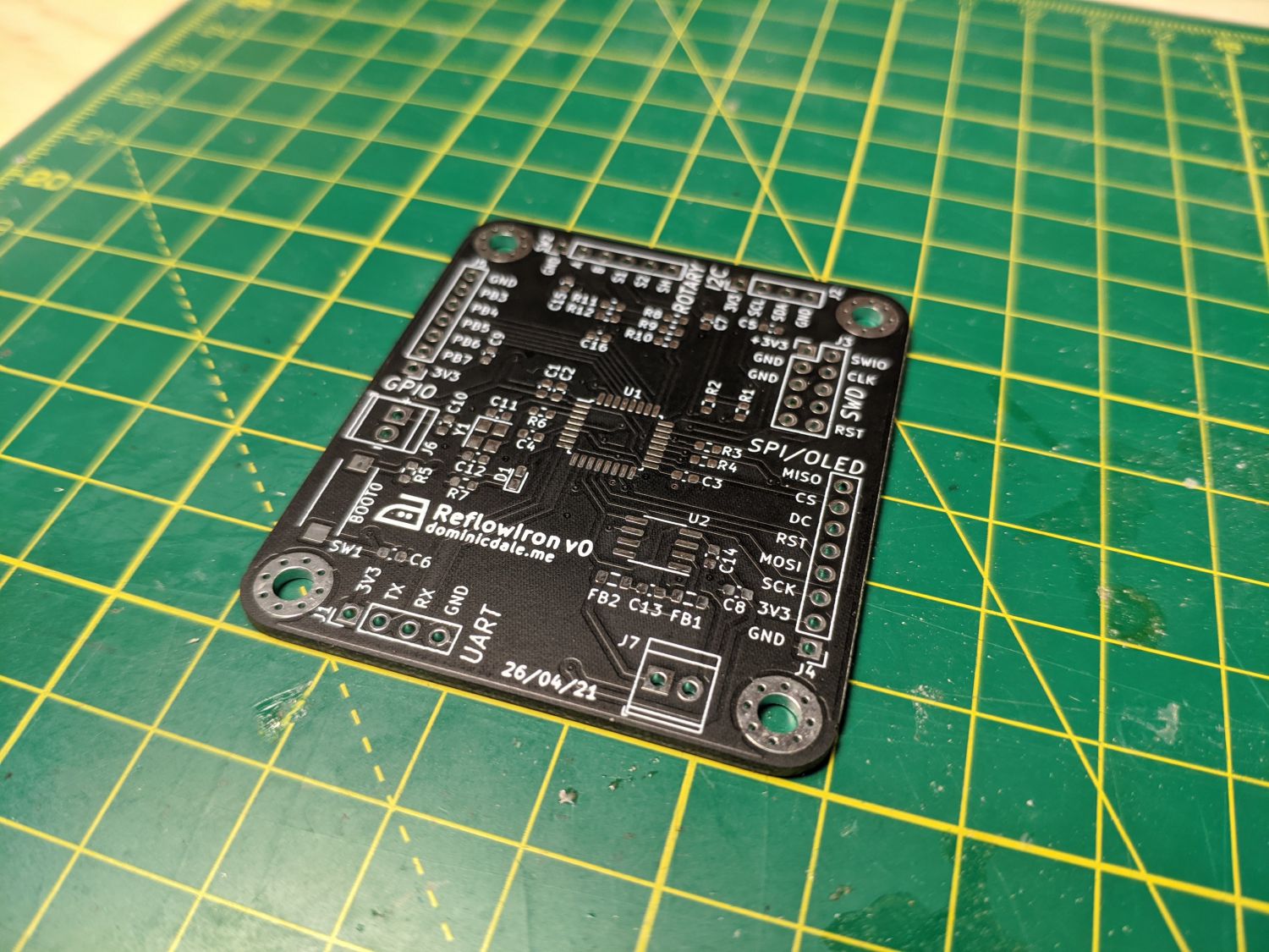
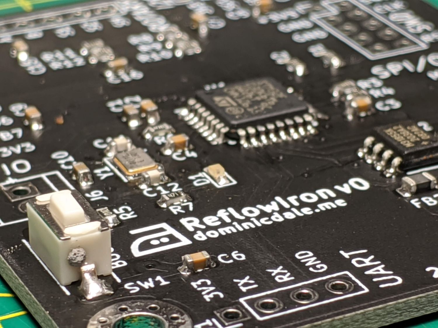
To finish, I moved around silkscreen labels, making sure references weren’t overlapping and adding extra names and details. I used KiCAD’s image converter to create the iron logo.
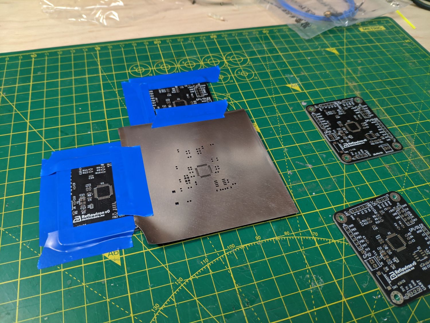
PCB assembly
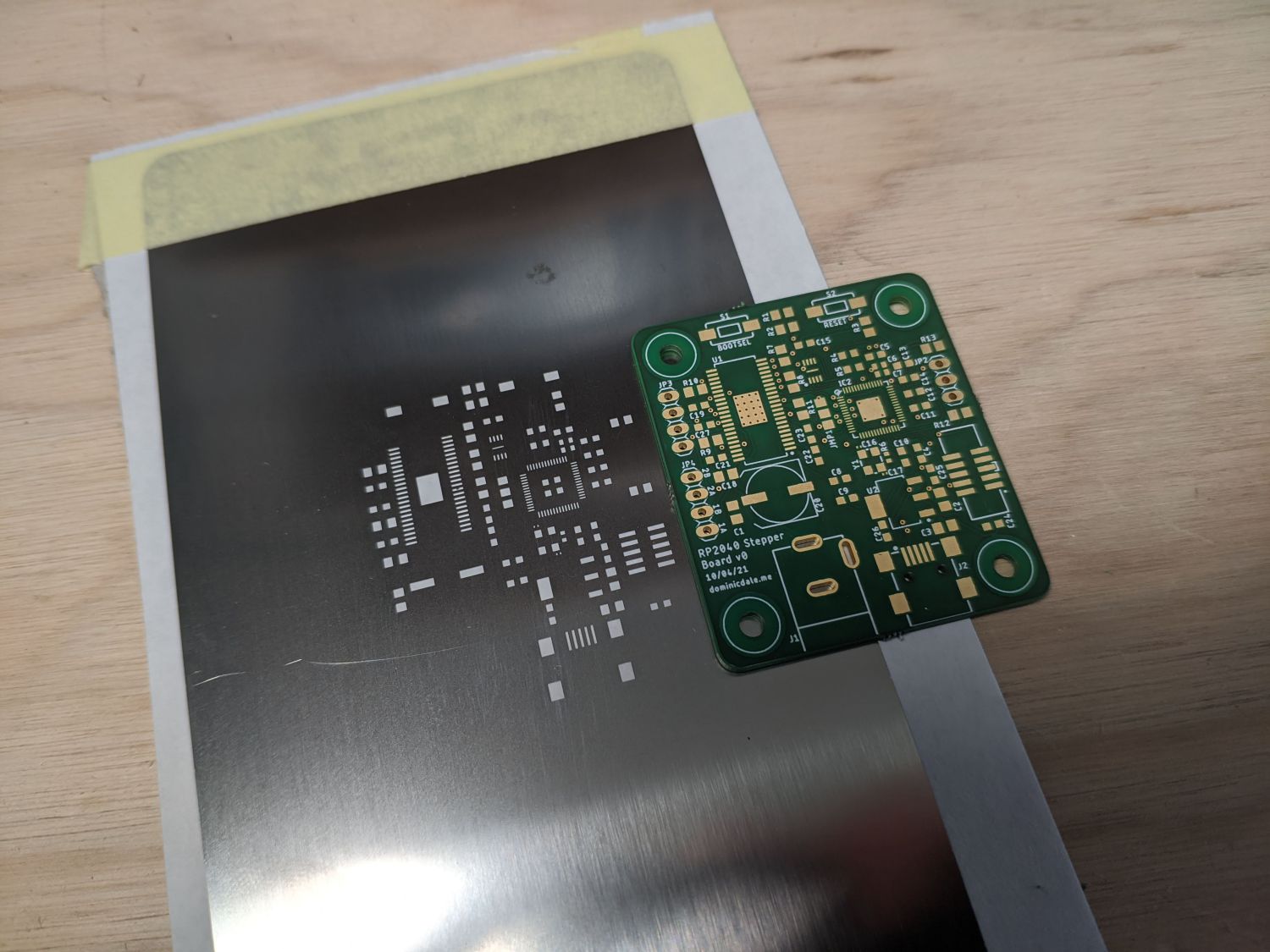
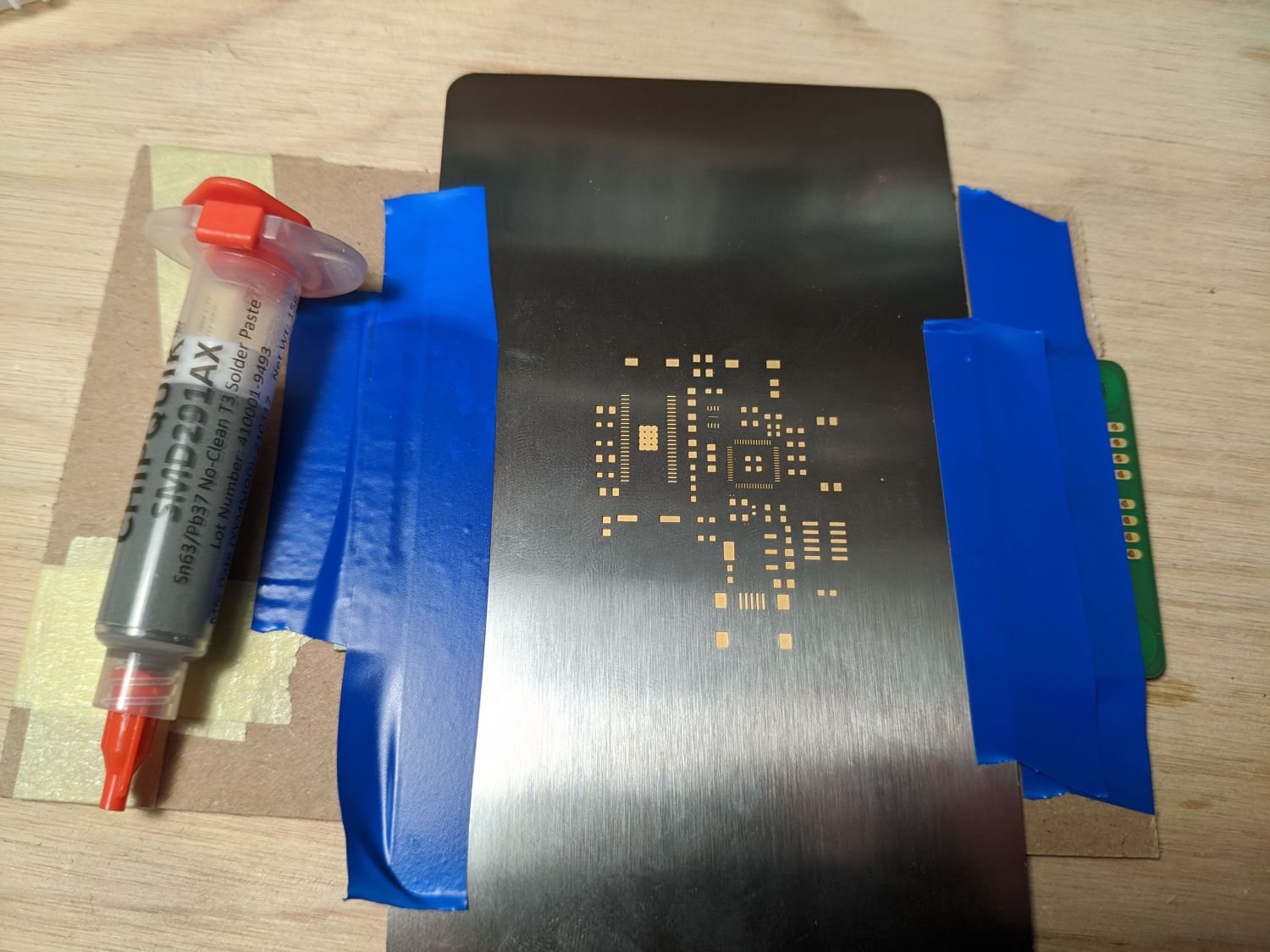
I had the PCBs manufactured by JLCPCB along with a stainless steel stencil. To keep the stencil at the right height I used the spare PCBs and taped everything down before aligning the actual PCB below it. Then I used a flexible card to scrape some high quality leaded solder paste across every pad.
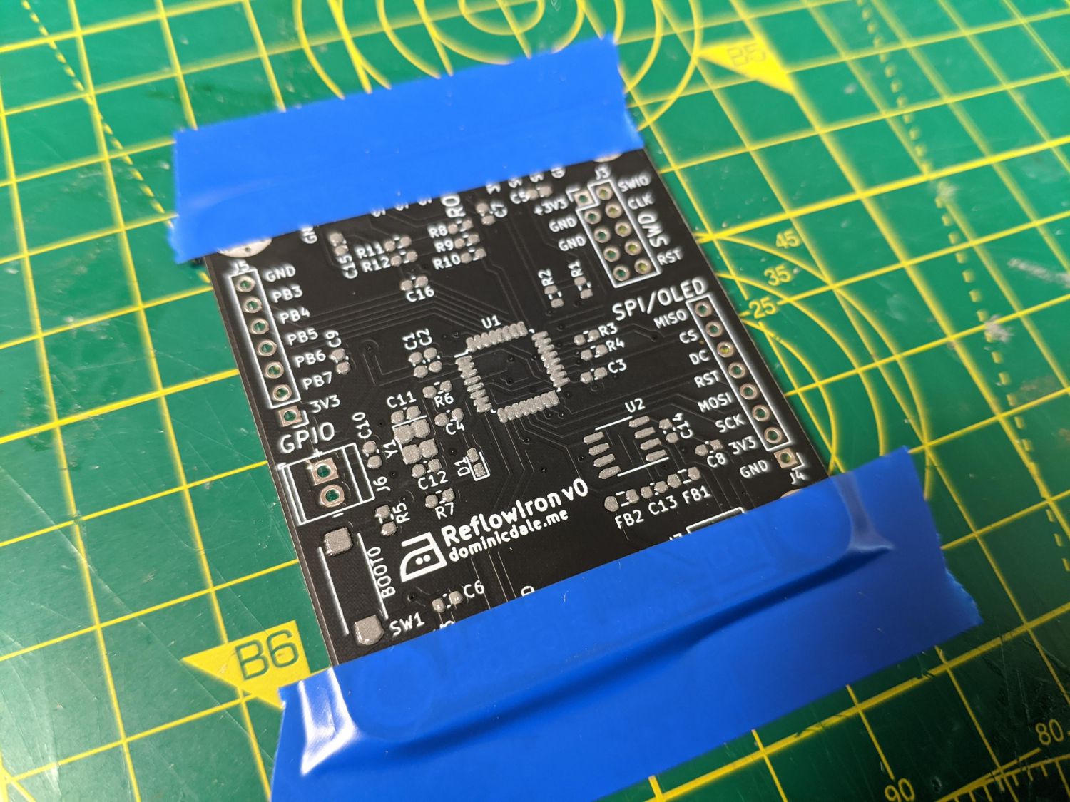
I used tweesers to manually place each of the many tiny SMT components with constant referral to the BOM. The KiCAD plugin InteractiveHTMLBOM made this much easier than it would have otherwise been. Once located the components are relatively stable as they are held down by the solder paste.
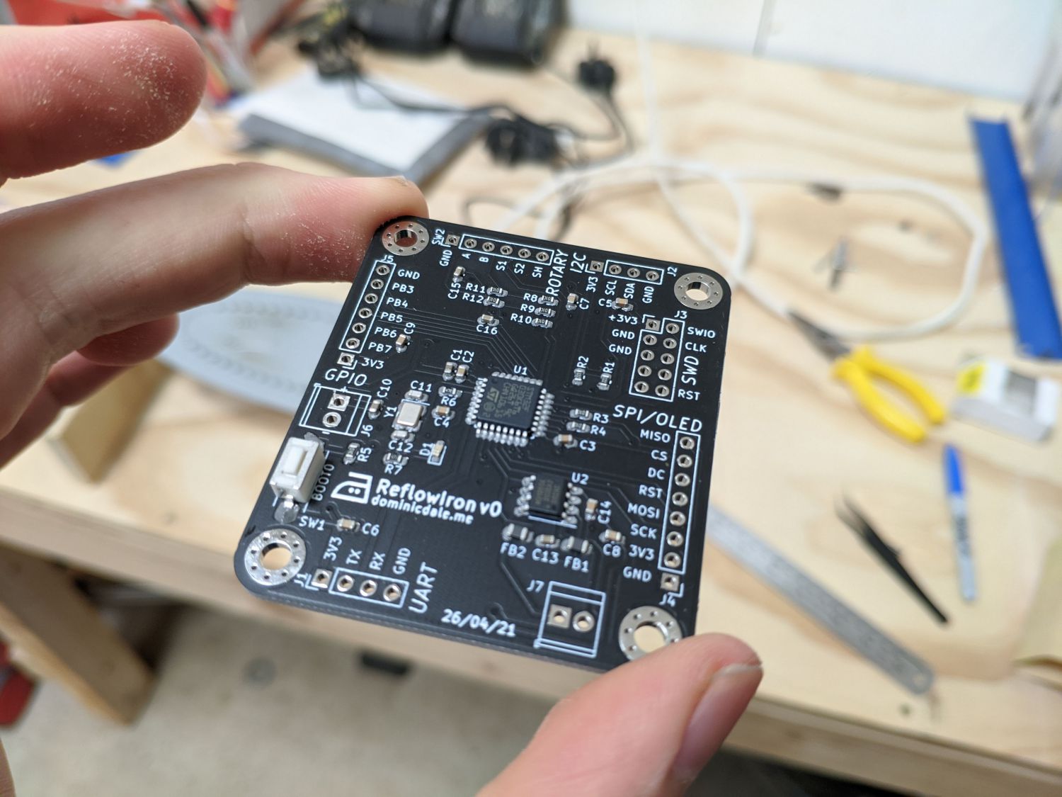
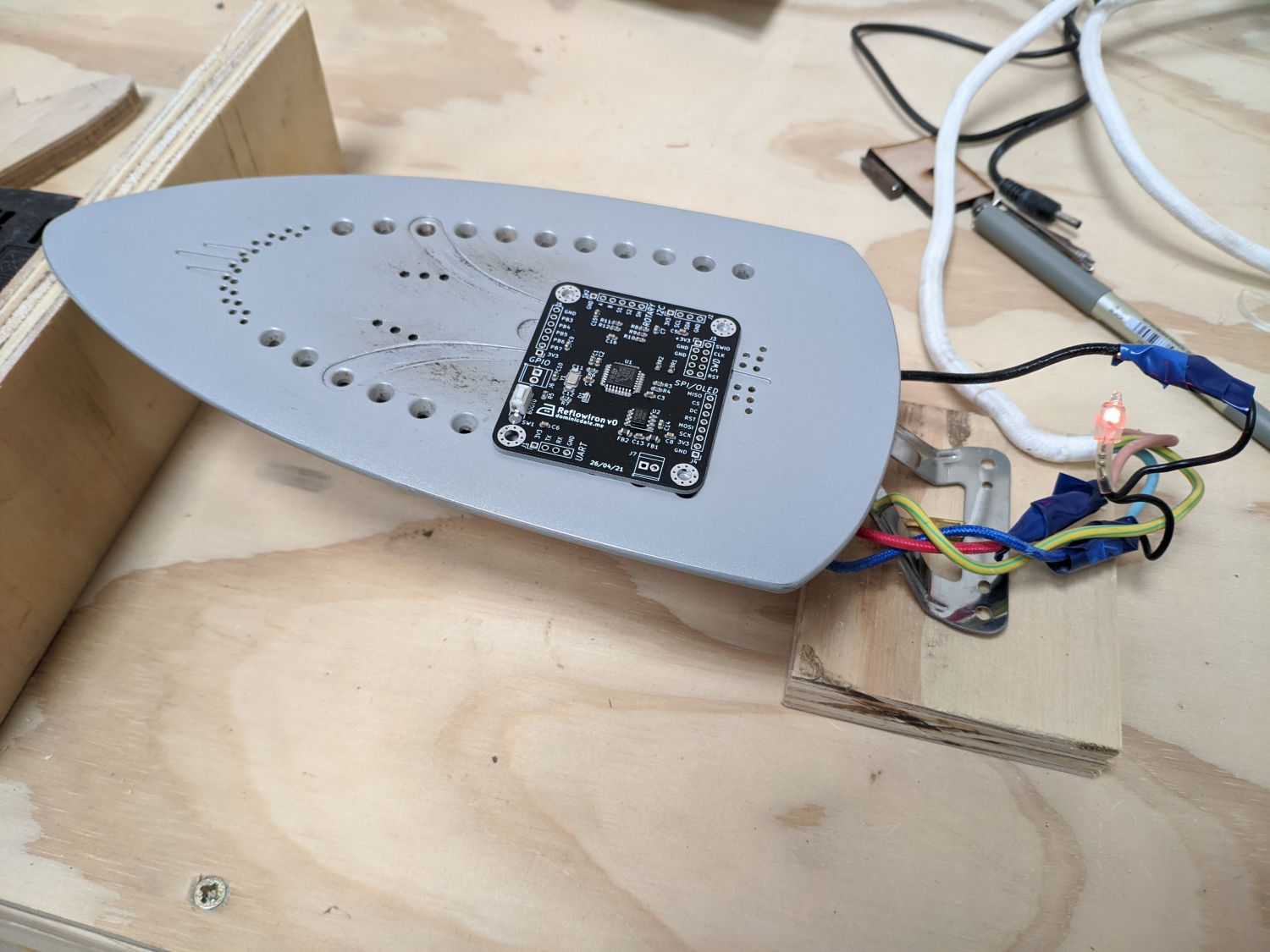
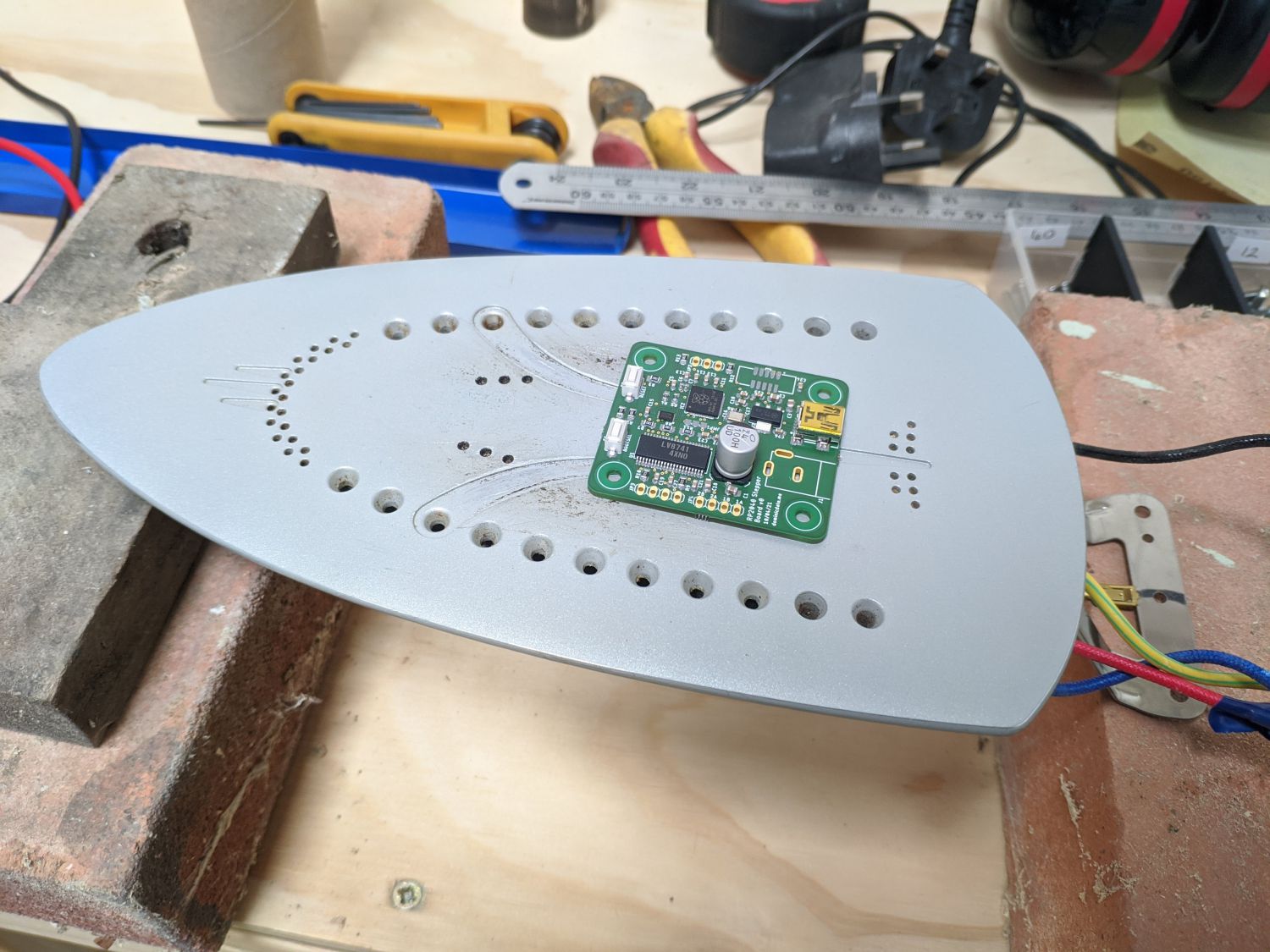
This was also a good opportunity to see if the iron would work at all to reflow full boards. With the fully populated PCB ready to go on the iron, I turned the power on at the wall and waited as it slowly heated. After a minute or so – and all at once – all of the small components reflowed; these were soon followed by larger pads.
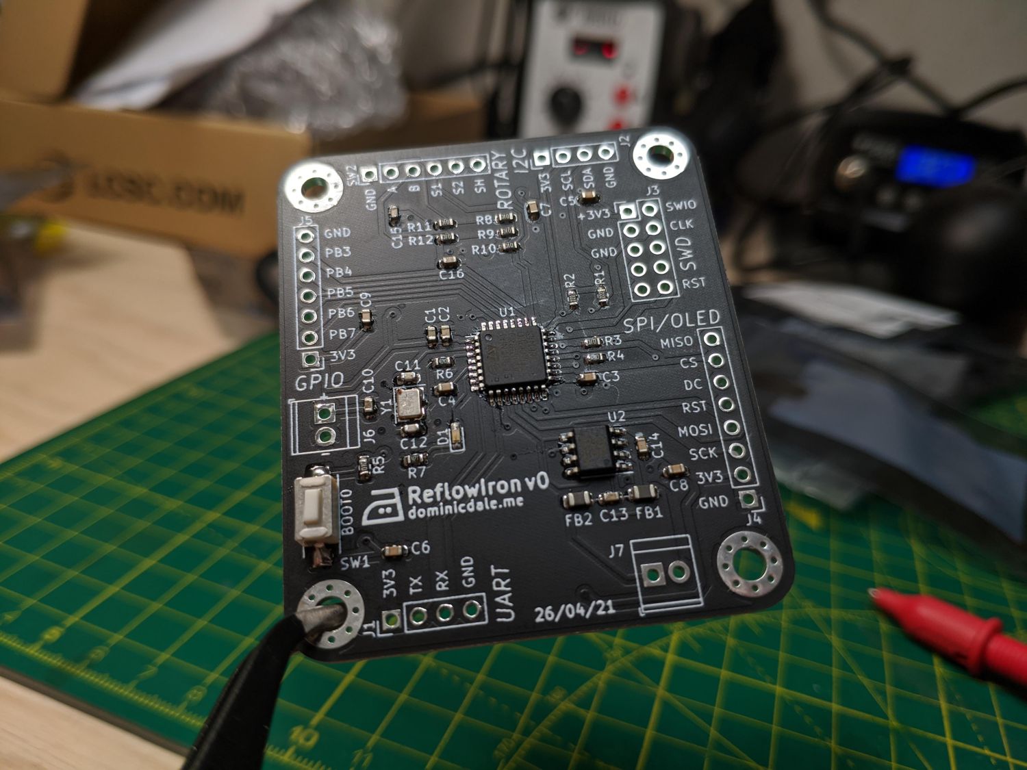
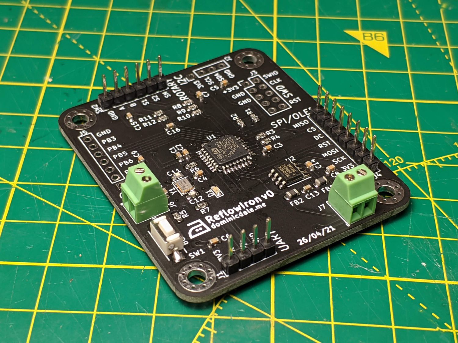
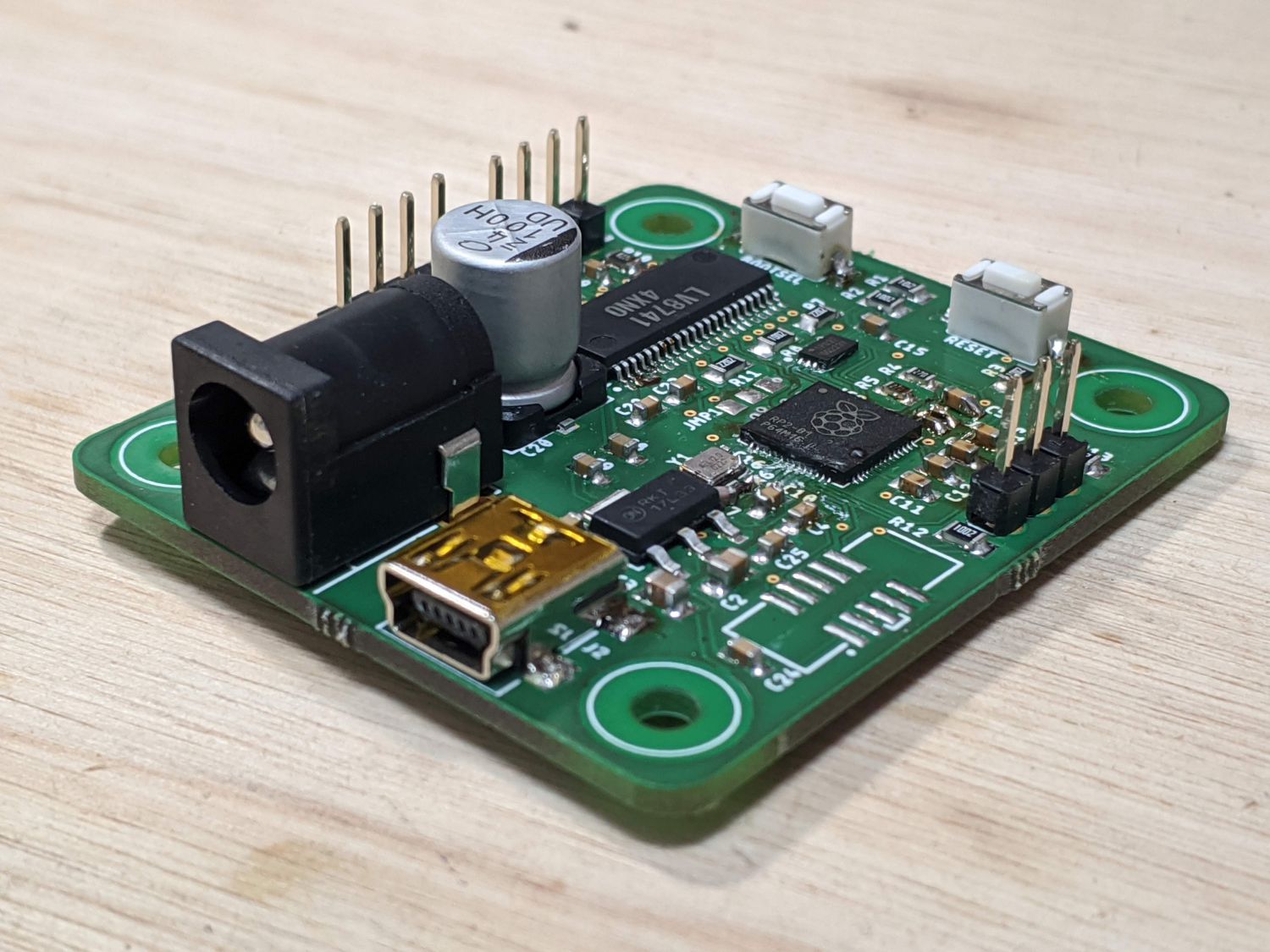
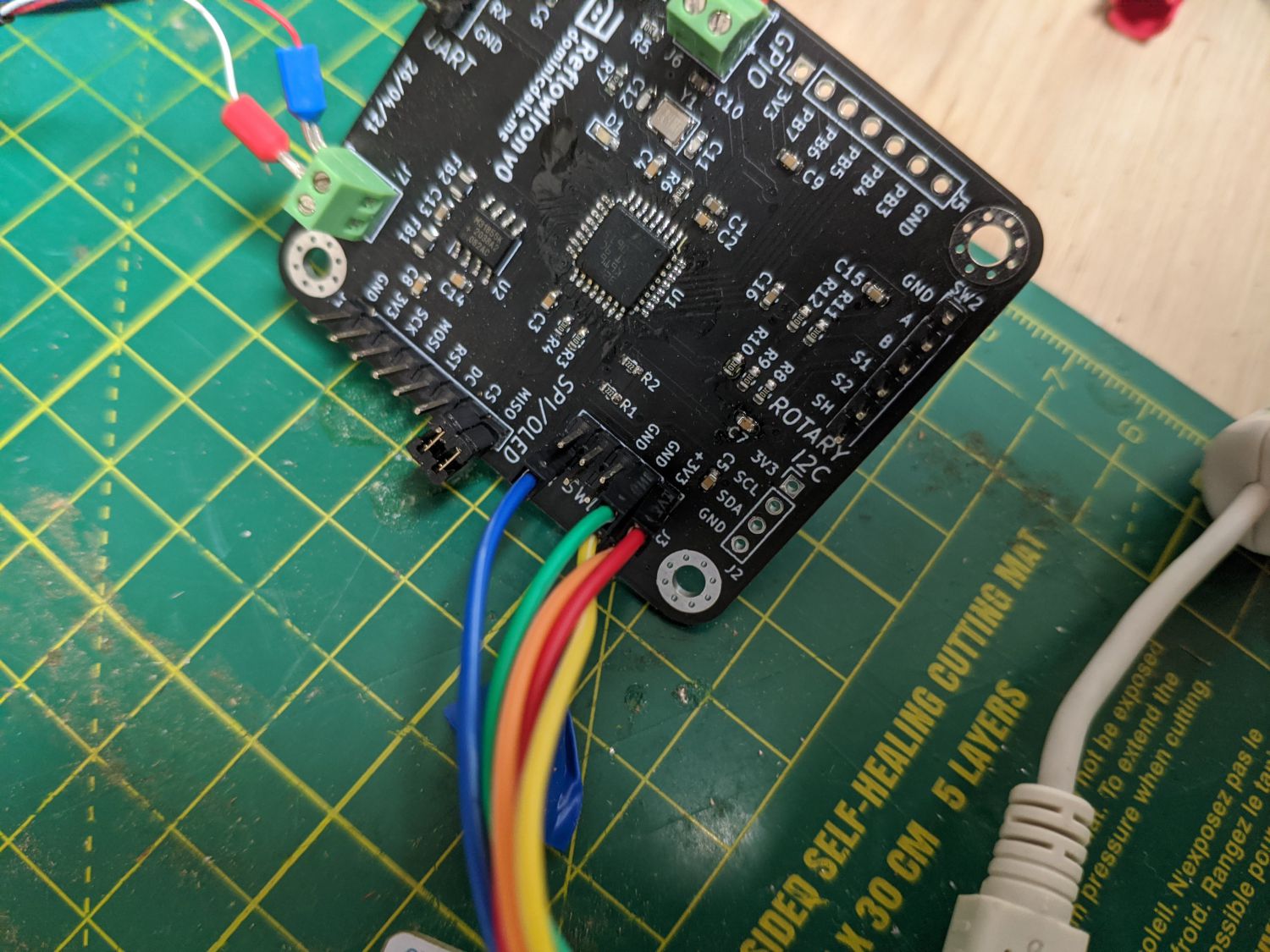
All I had left to do was add the THT terminals and headers.
Software
While the full software is still in development at the time of writing, I did test a few basic drivers to make sure the hardware was functioning properly.
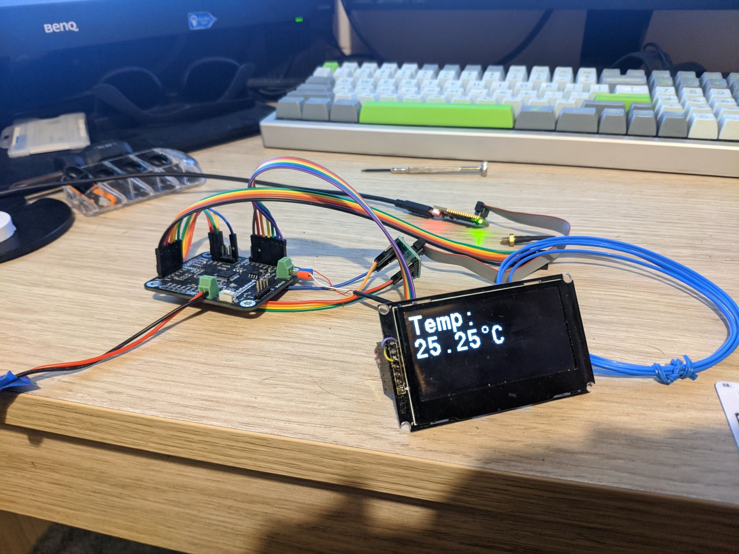
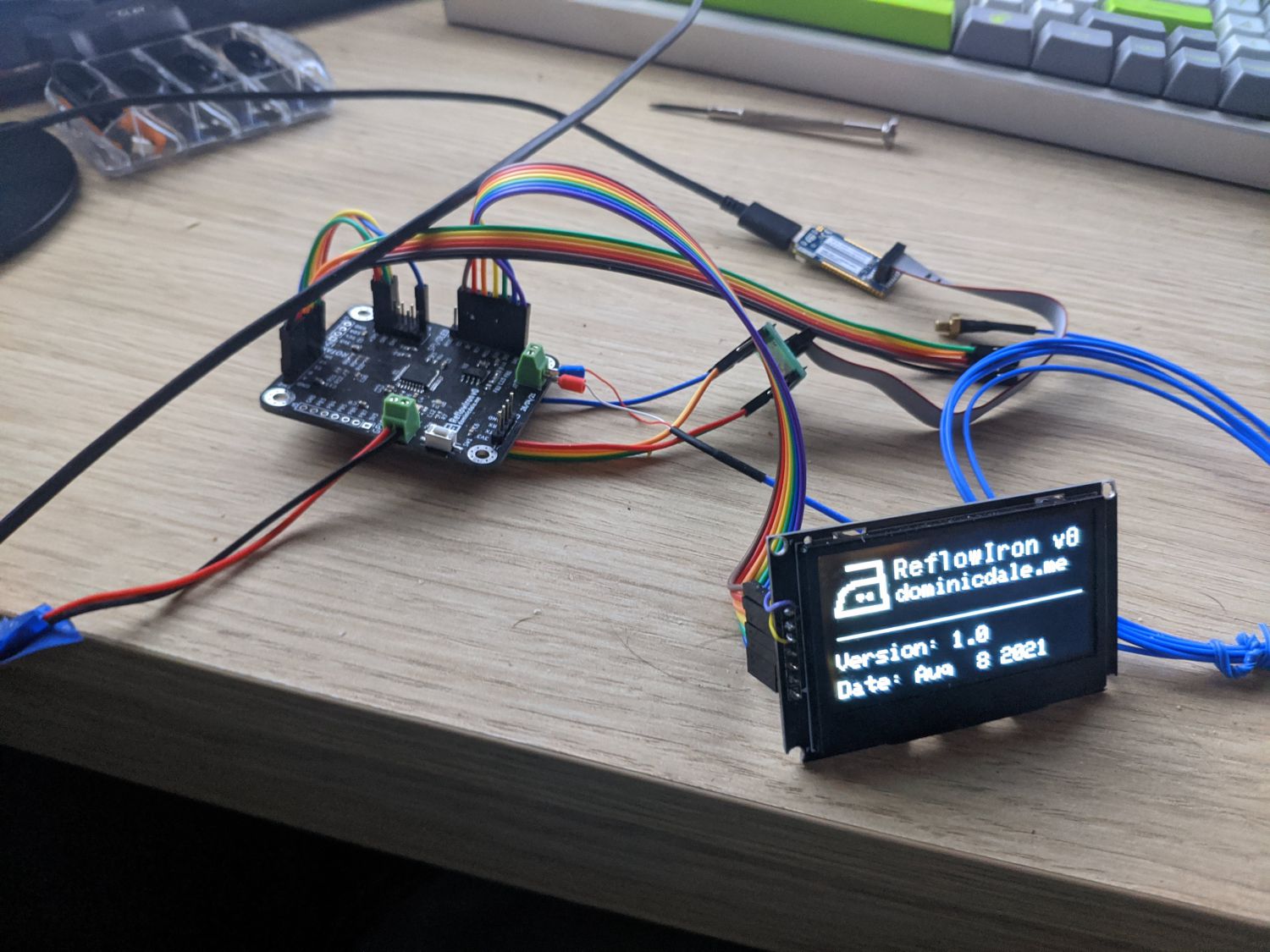
Temperature reading, OLED output and I/O all worked as expected.