Having completed the clock design (see this previous post), I needed to manufacture the three main components: the control circuit, the matrix circuit and the casing.
Control circuit
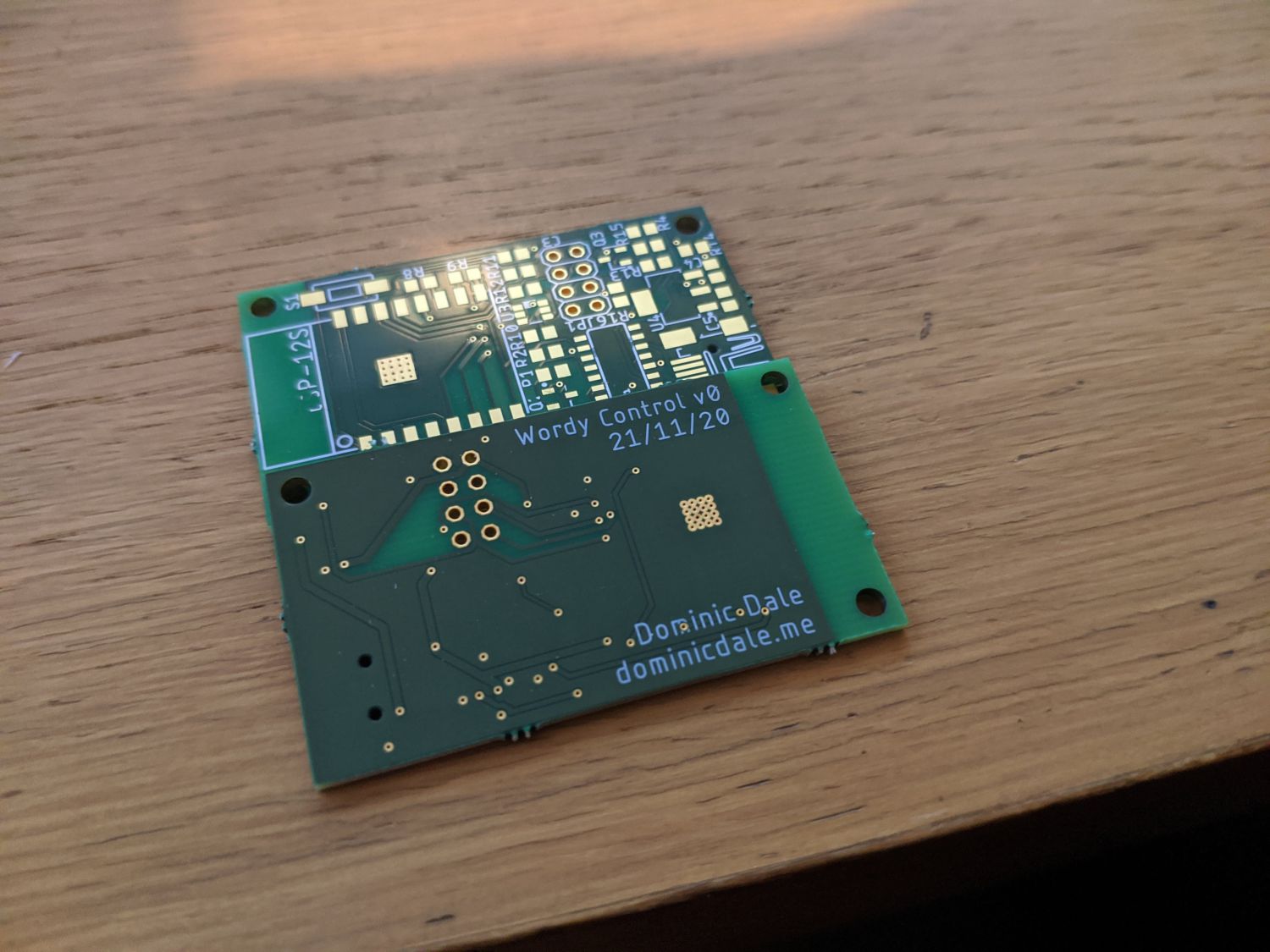
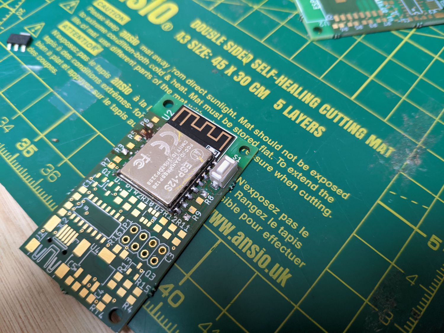
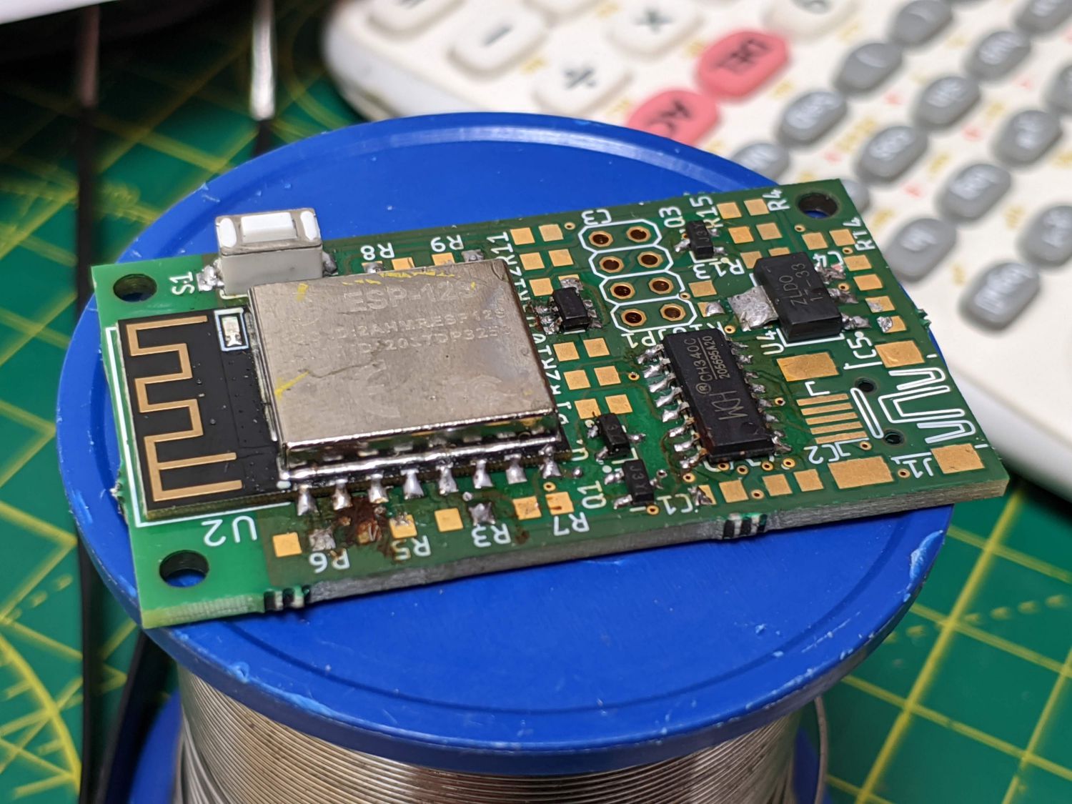
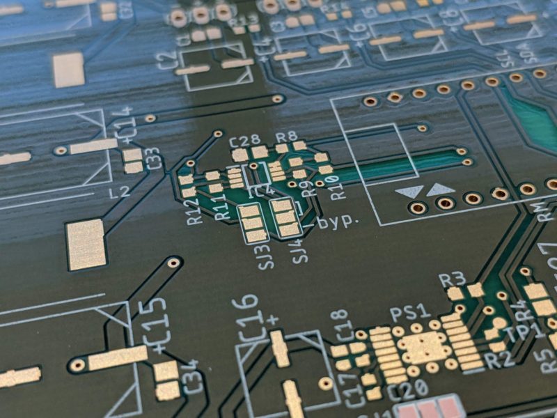
I soldered the SMT control board starting with the smallest components and working my way up. A BOM exported from Eagle came in useful to identify components based on their reference designators.
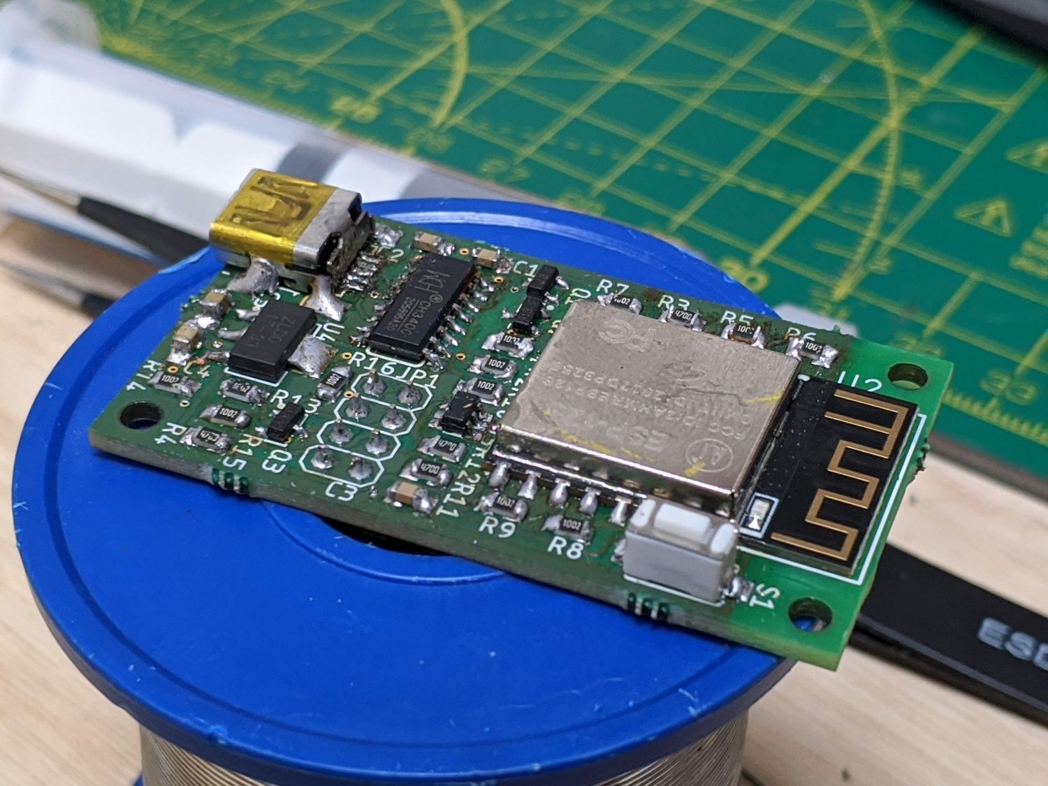
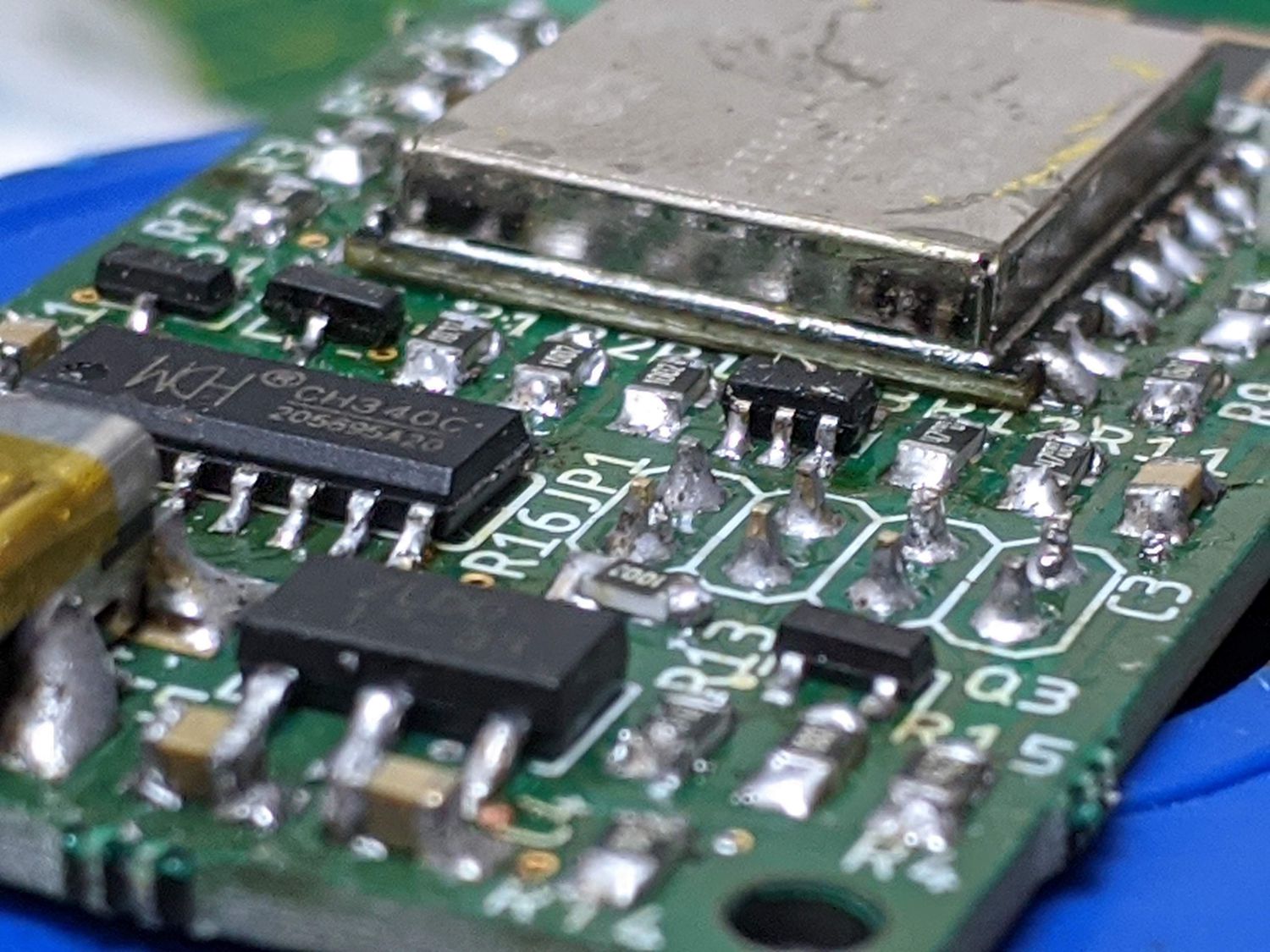
The USB connector had the finest pitched pins so for this package, and the other ICs, I used solder paste. I used ‘0805’ sized passives which were easy enough to solder using tweezers and a chisel tip.
As mentioned in the design article, I made a number of mistakes routing the USB lines so used some wire wrapping wire to reroute these traces.
LED matrix
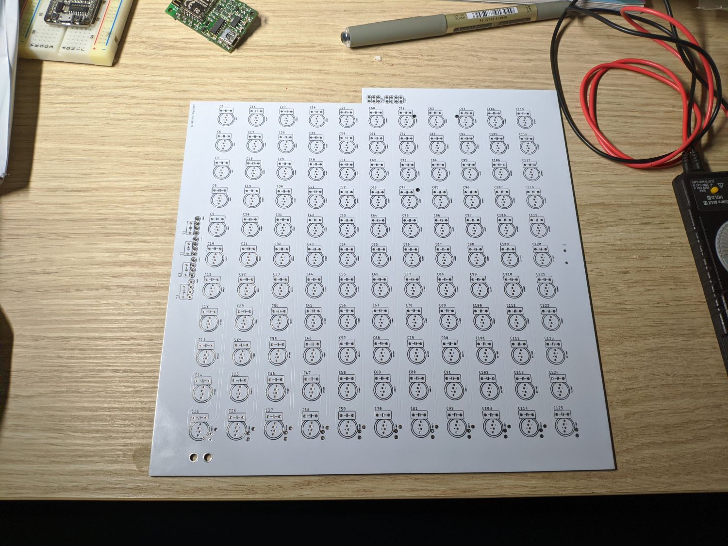
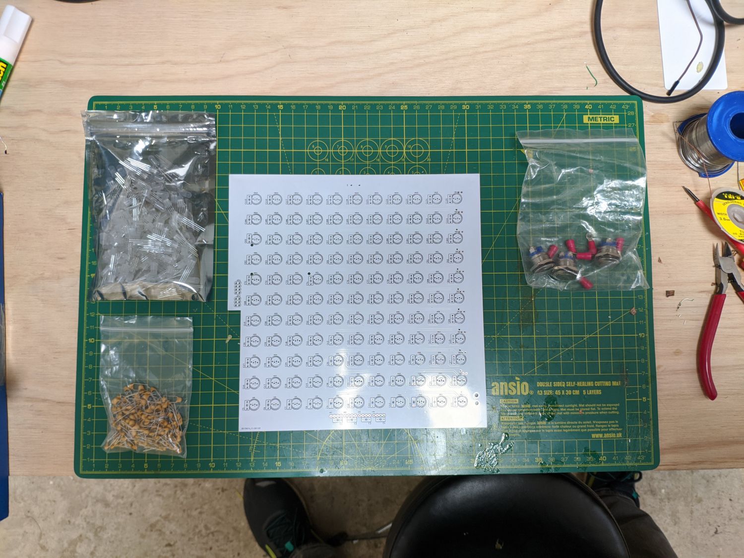
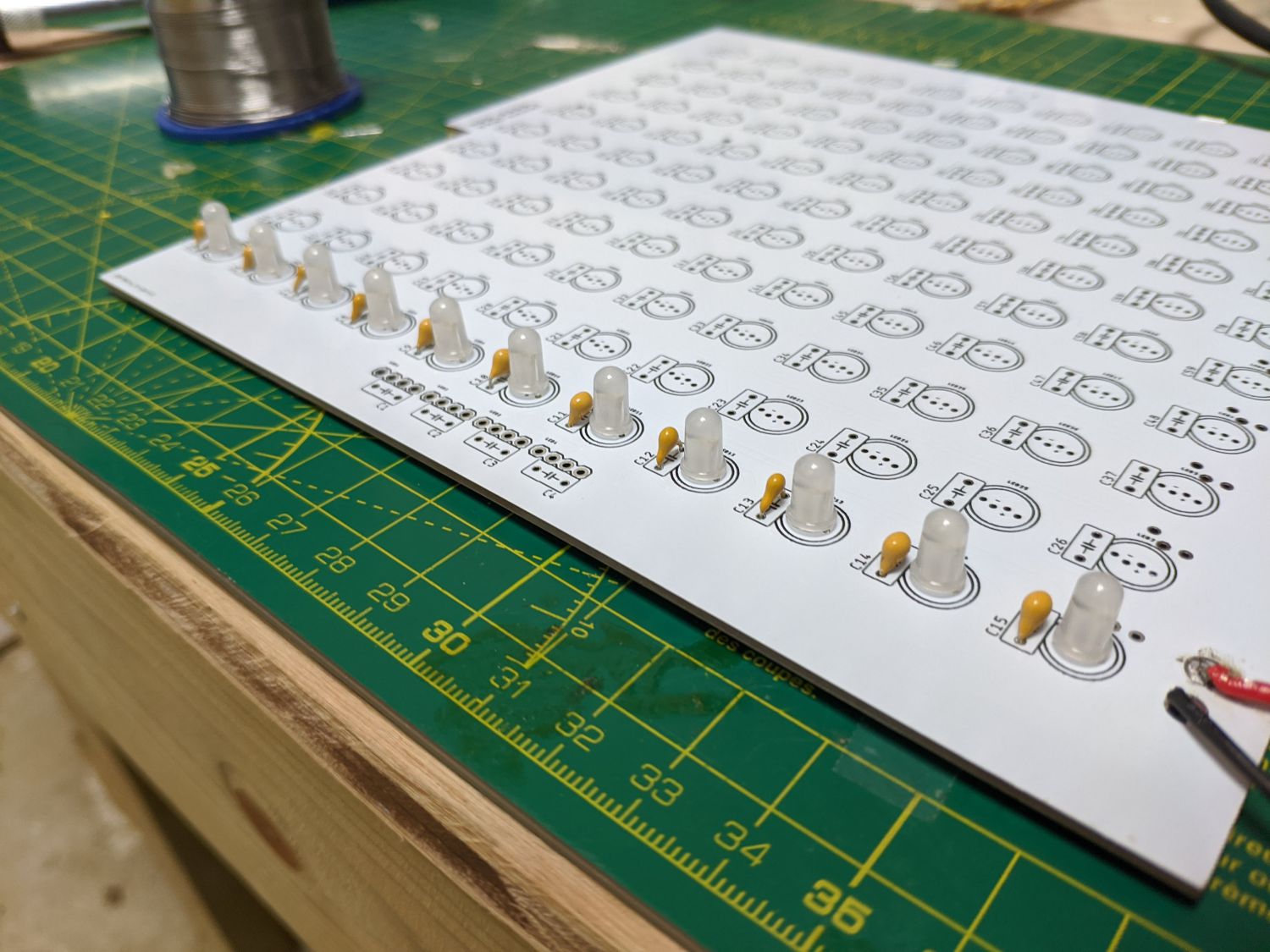
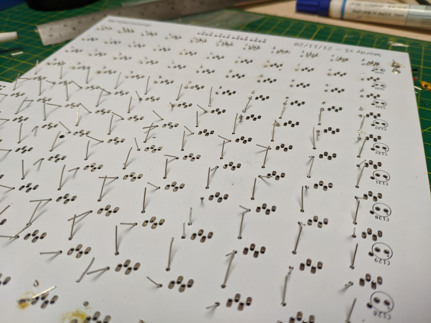
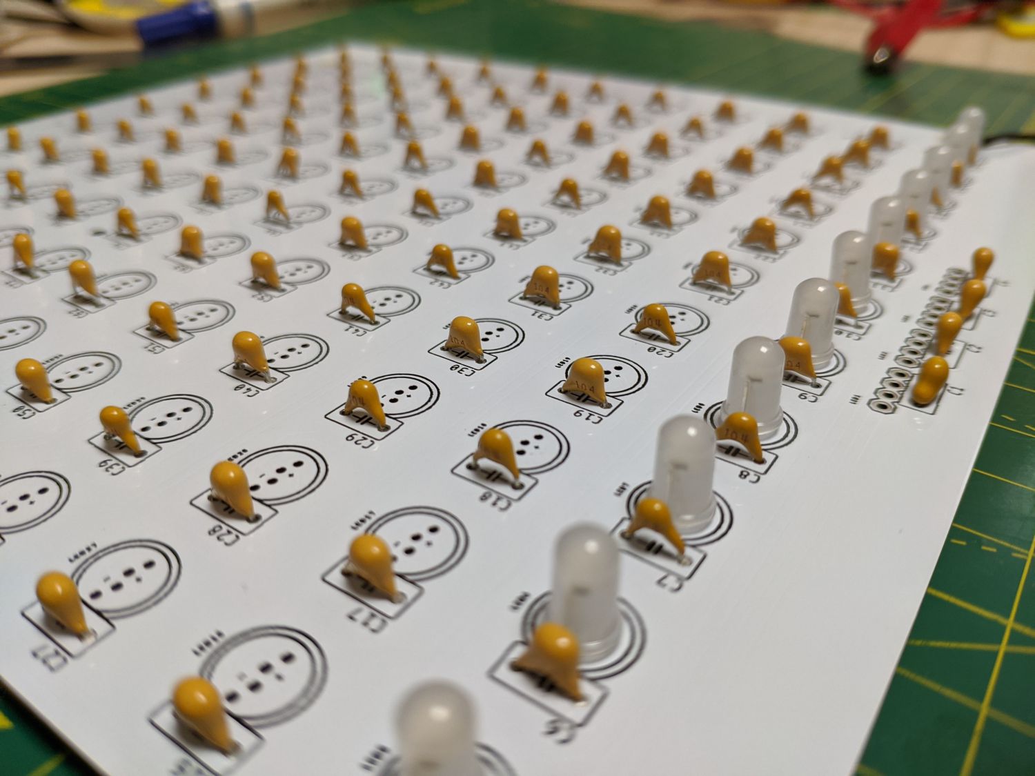
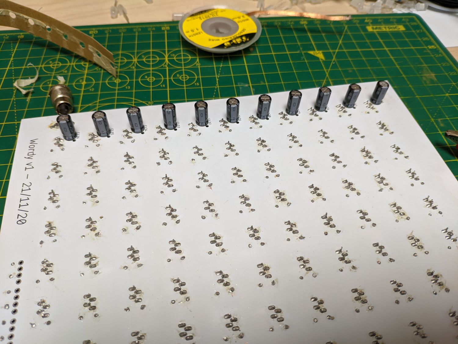
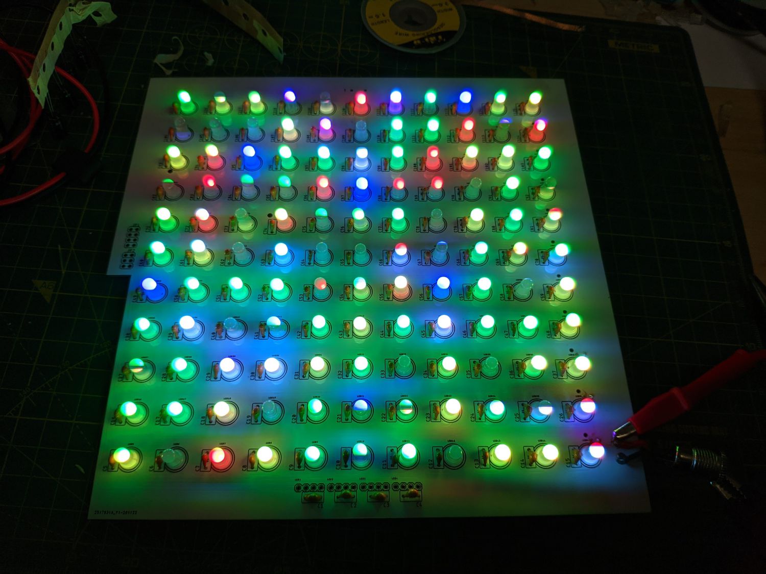
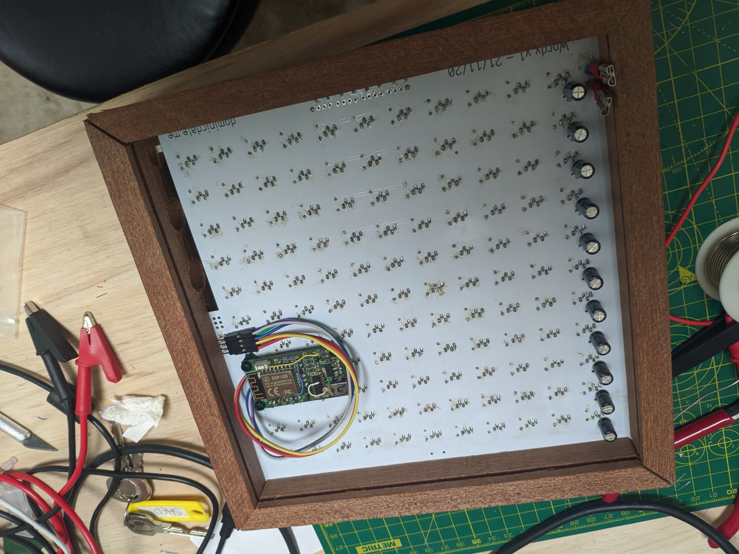
I had the PCB manufactured with white soldermask to maximise reflectivity. For assembly, it was just a case of working my way down each row soldering a capacitor and LED for every letter. If I designed this again I would avoid the through hole parts as it was tedious bending the legs of all the components.
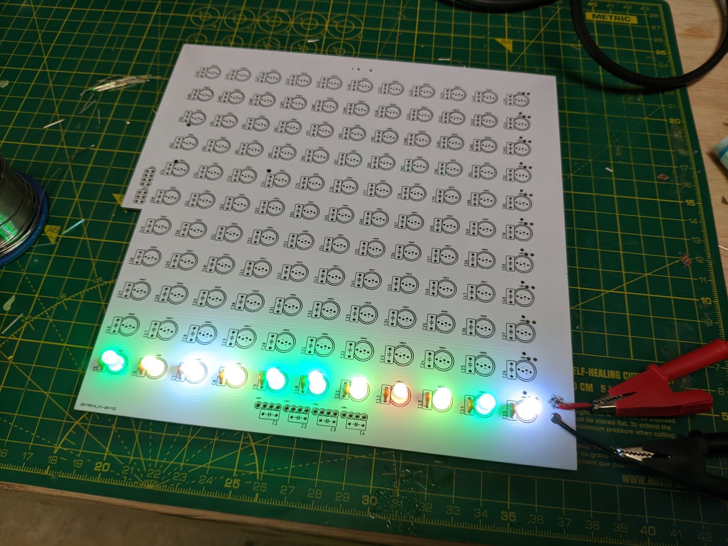
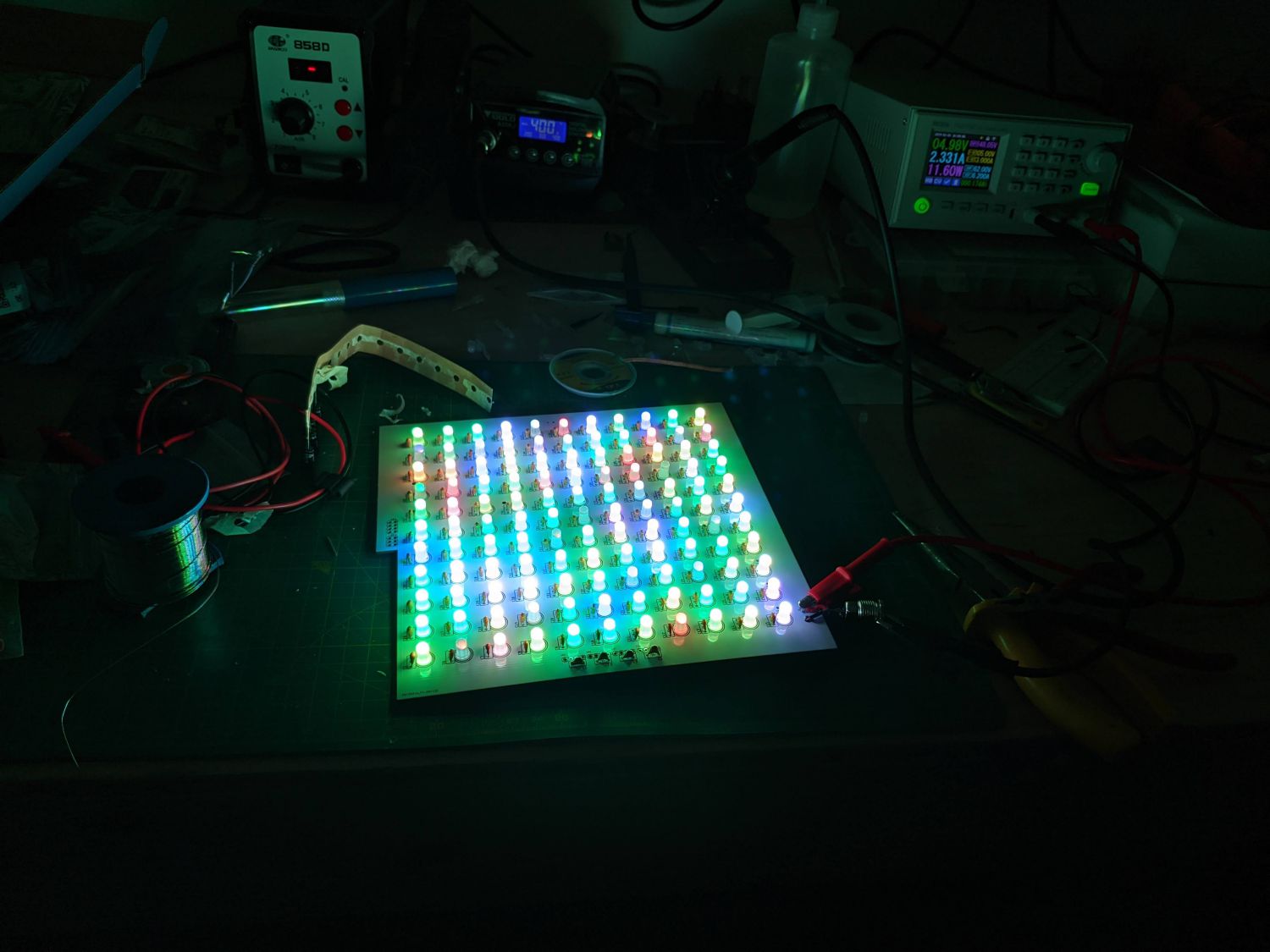
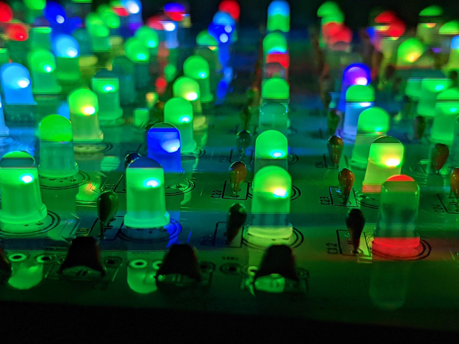
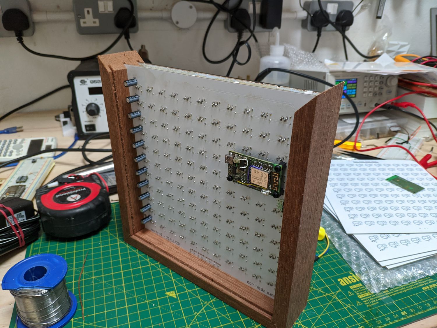
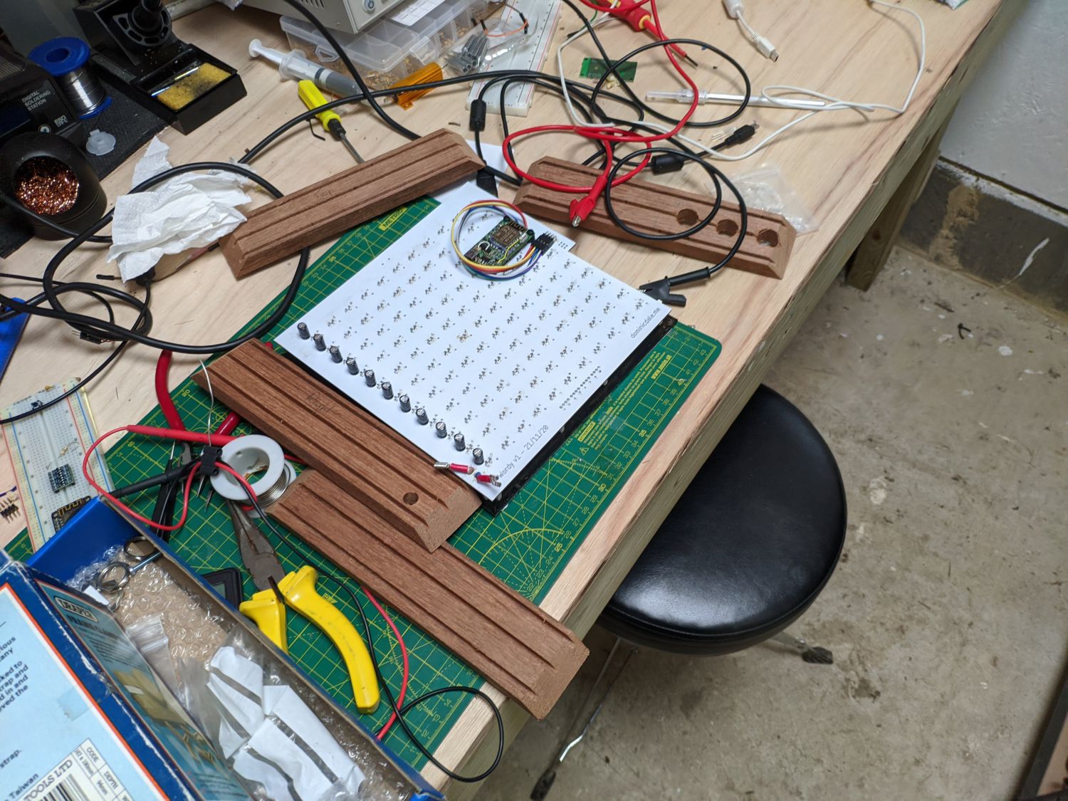
A current limited bench power supply came in handy for testing the board without the risk of damaging components if I’d made any mistakes. With no data input, the WS2812Bs display an interesting cycle of random colours.
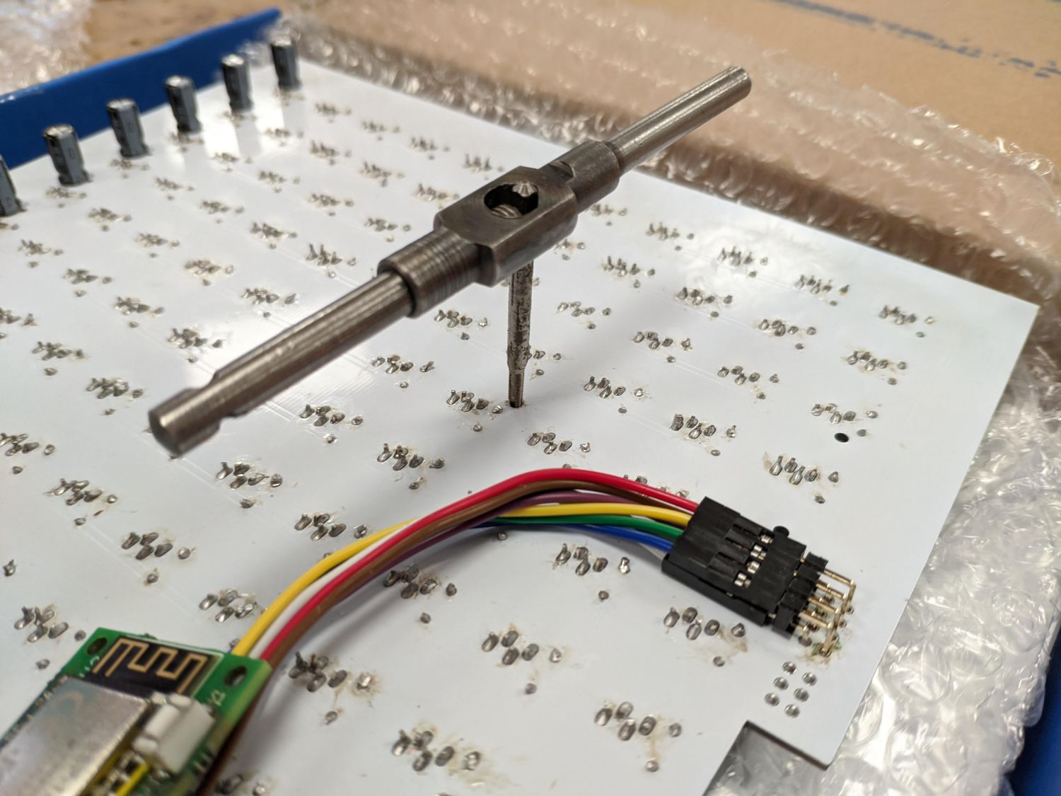
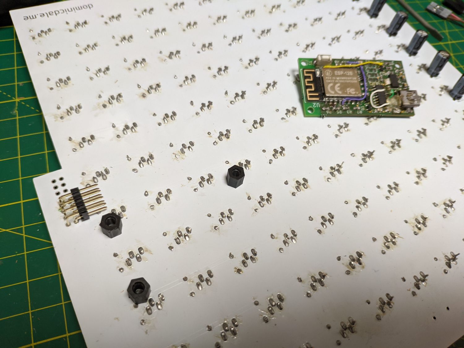
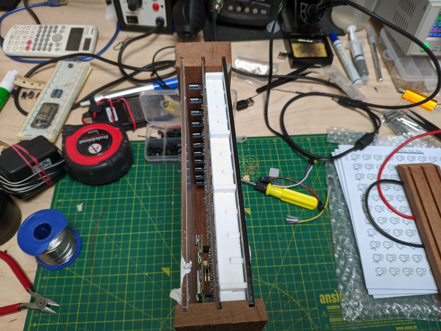
To mount the control circuit to the main matrix PCB, I included three NPTH in the layout. No hardware can protrude through the front of the matrix PCB as it would interfere with the grid, so instead I tapped M3 threads in each of the holes and used nylon standoffs to fix the controller. The mount is located near to the 2.54mm interfacing header that connects the two boards.
With everything together I loaded some test FastLED code on to the board and everything worked as expected.
Casing
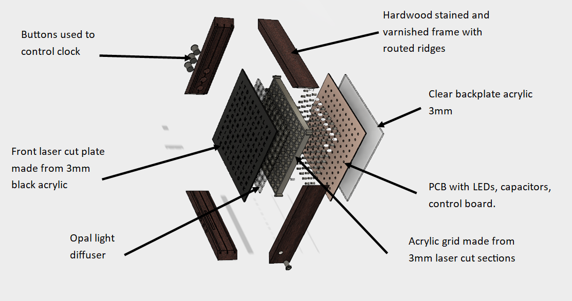
To turn this set of PCBs into a proper clock I needed to manufacture the mechanical chassis. First, a reminder of the construction:
The first step was to later cut the clock face from 3mm black acrylic. I did this using a 40W CO2 laser.
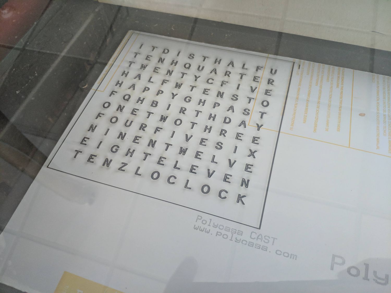
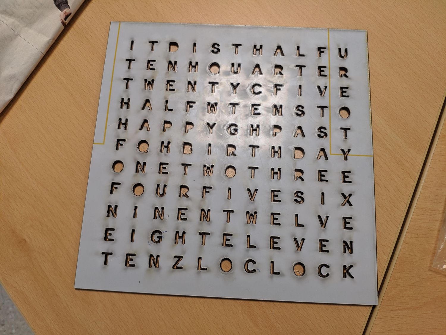
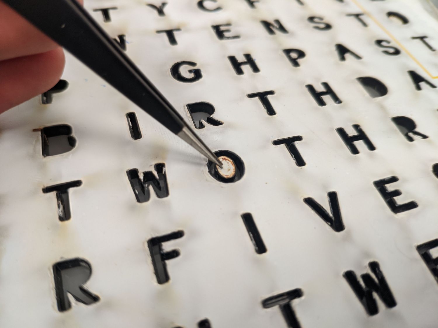
Because I had opted to use a font with ‘islands’ many of the letters fell out (e.g. the ‘O’s) and I had to collect them for later glueing.
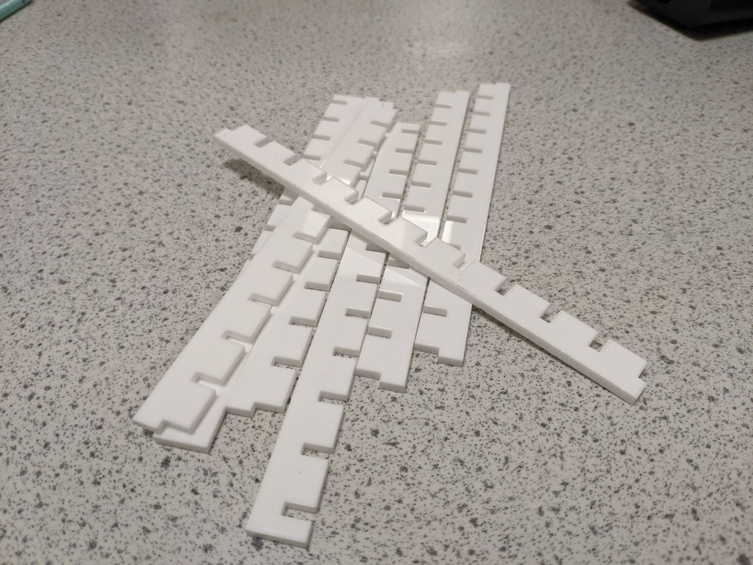
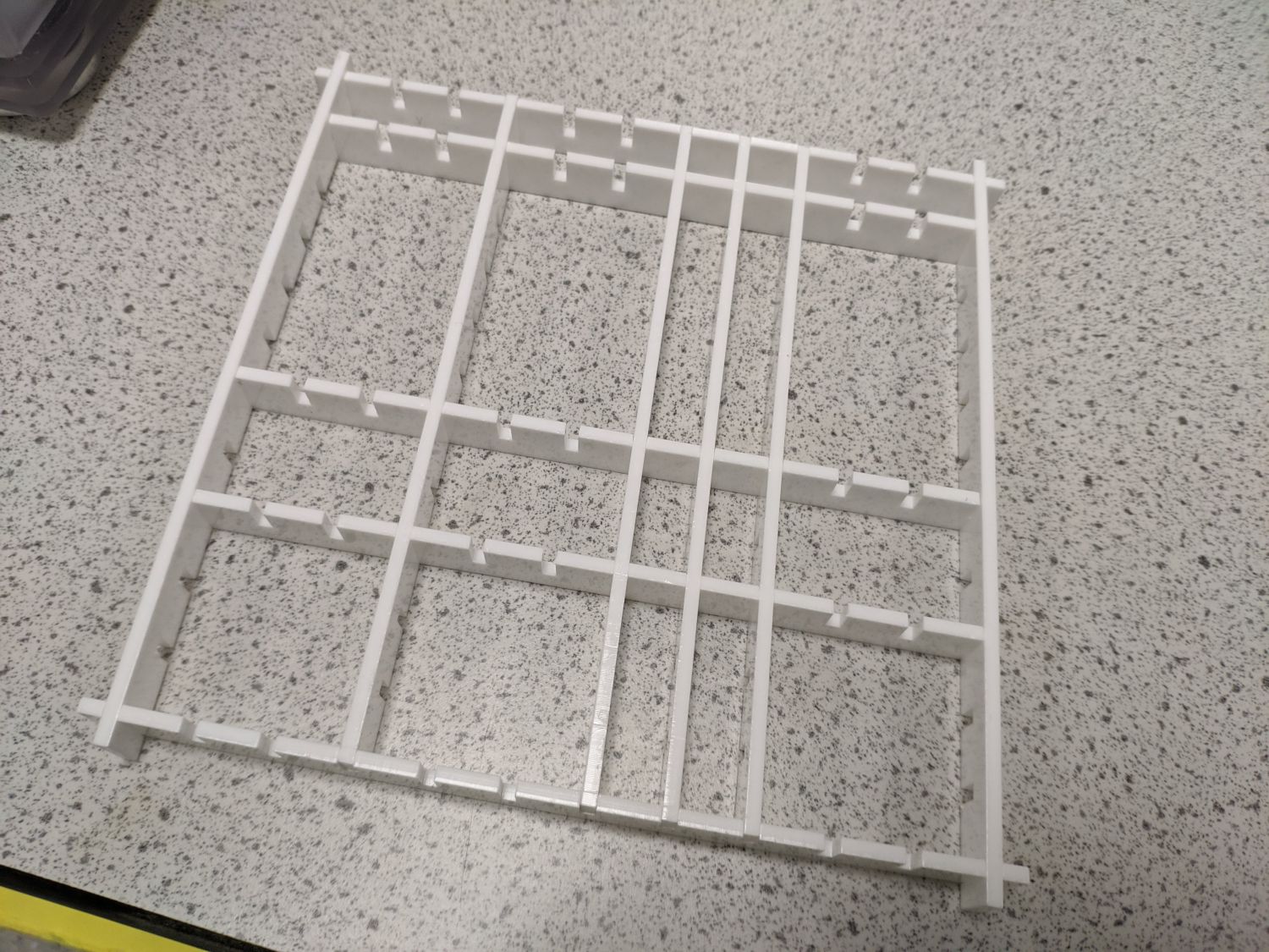
I also decided to laser cut the grid that would contain the light from each LED to a single letter. This later proved to be the critical flaw of this prototype iteration.
I laser cut the acrylic opal diffusers and back plate using the same machine.
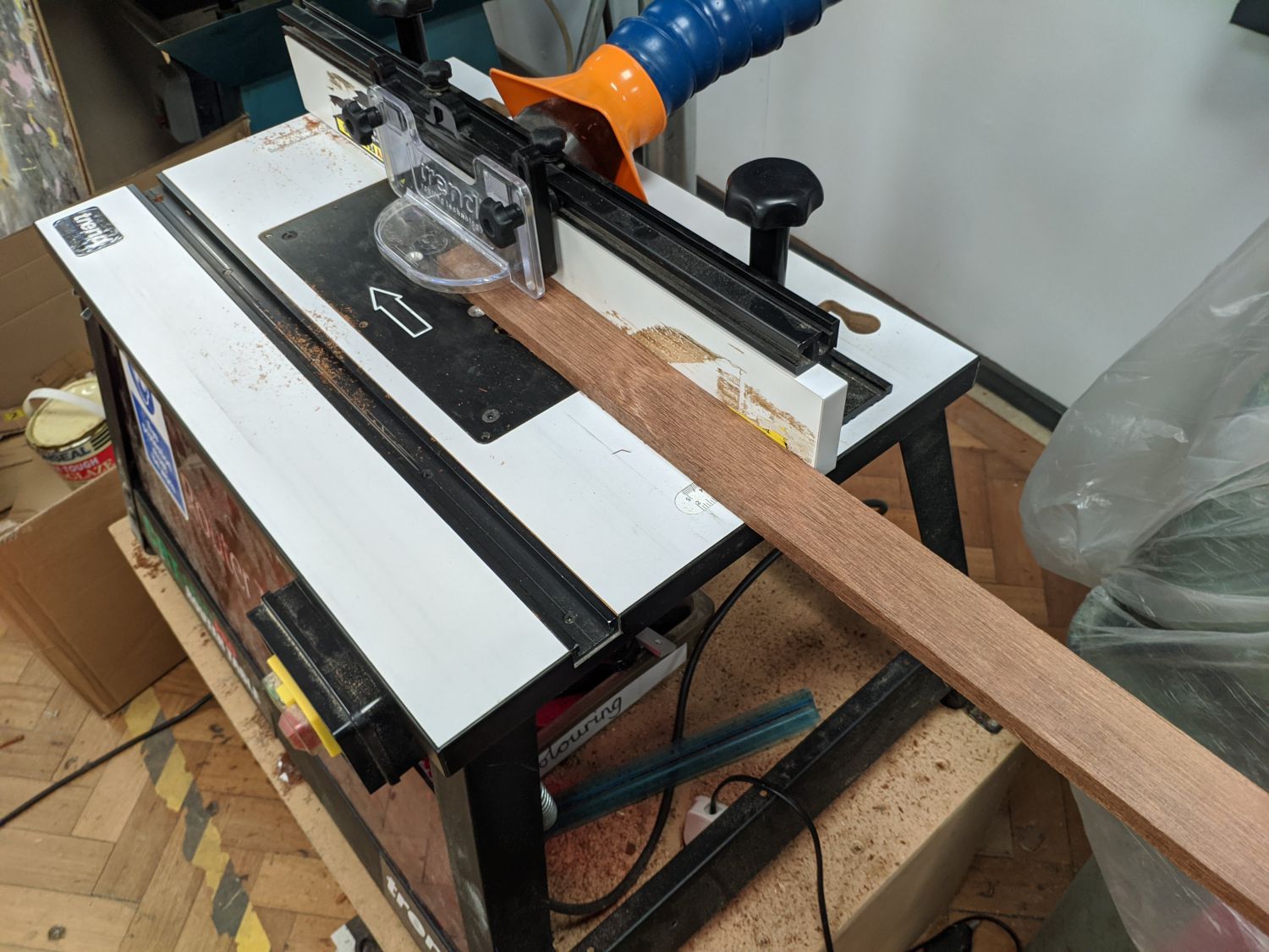
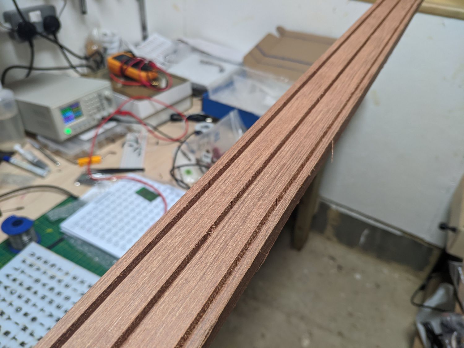
To create the border I found some scrap tropical wood and dimensioned it with a planer thicknesser. I then used a router table with a 3mm straight flute cutter to create the grooves that capture the PCB, face and back plate.
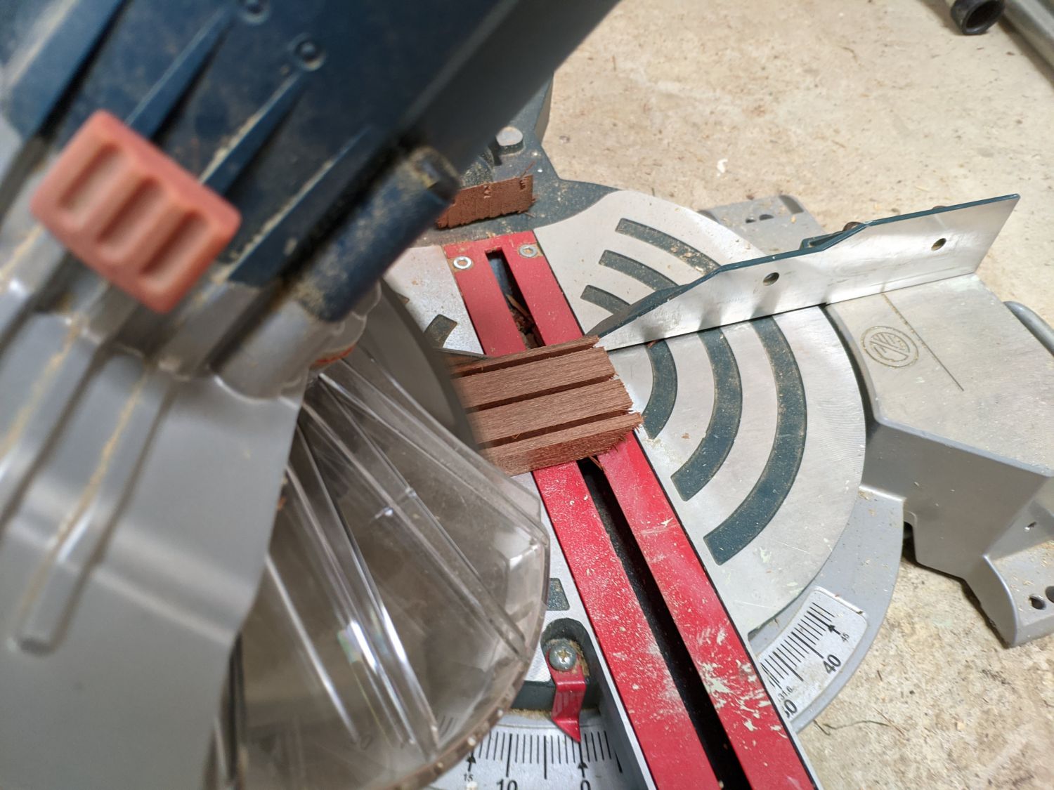
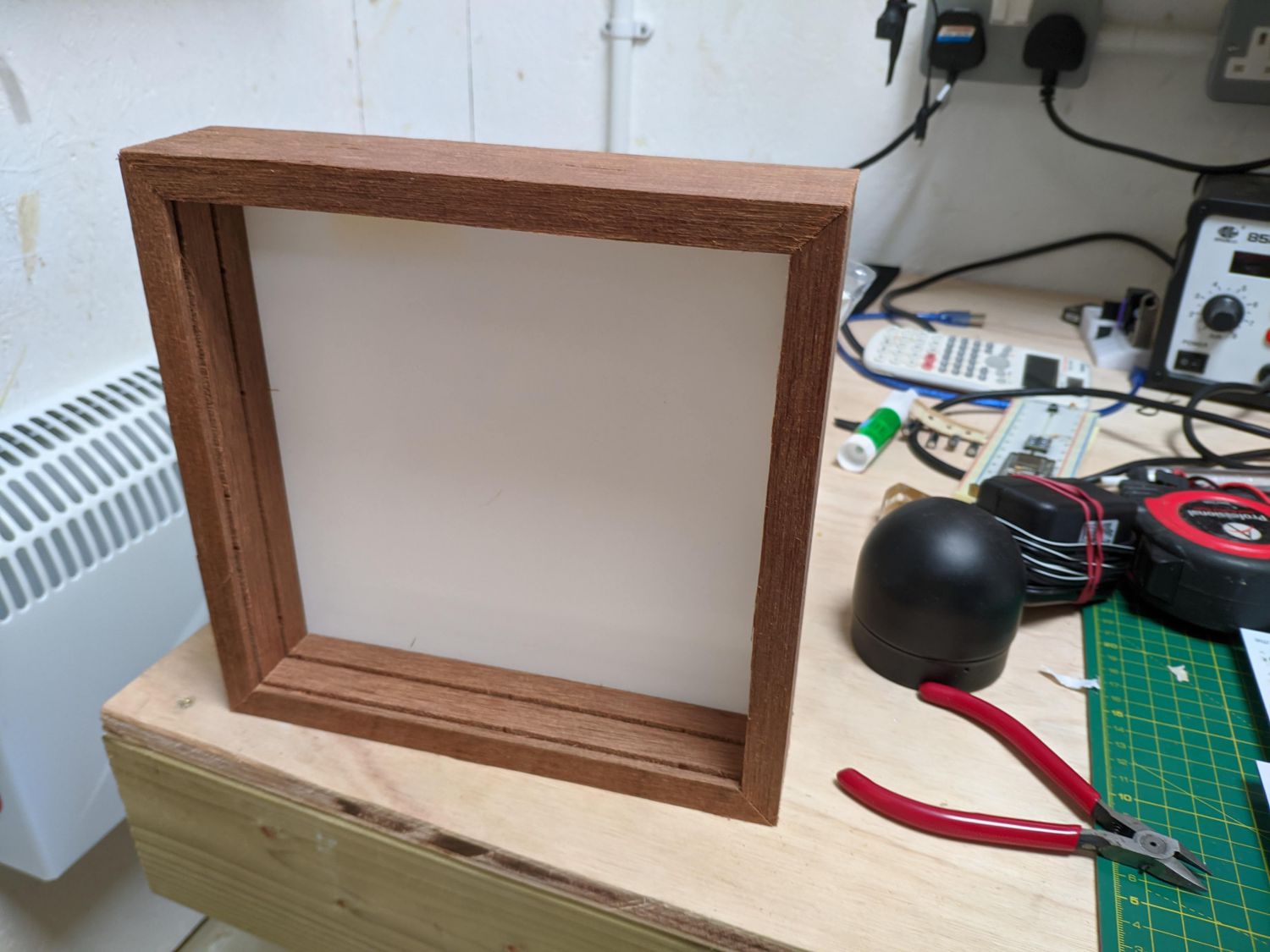
I could then use my mitre saw to cut the borders to length at a 45° angle. The first test fit with the back plate looked promising!
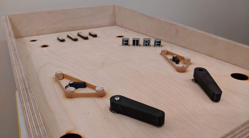
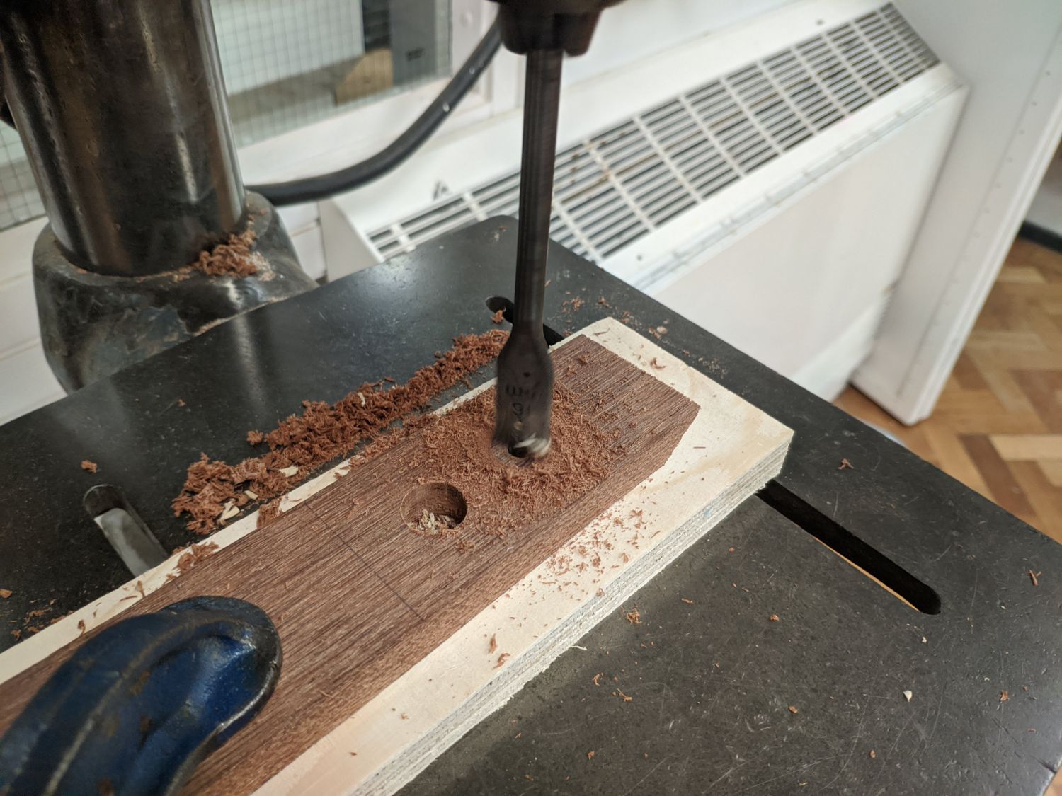
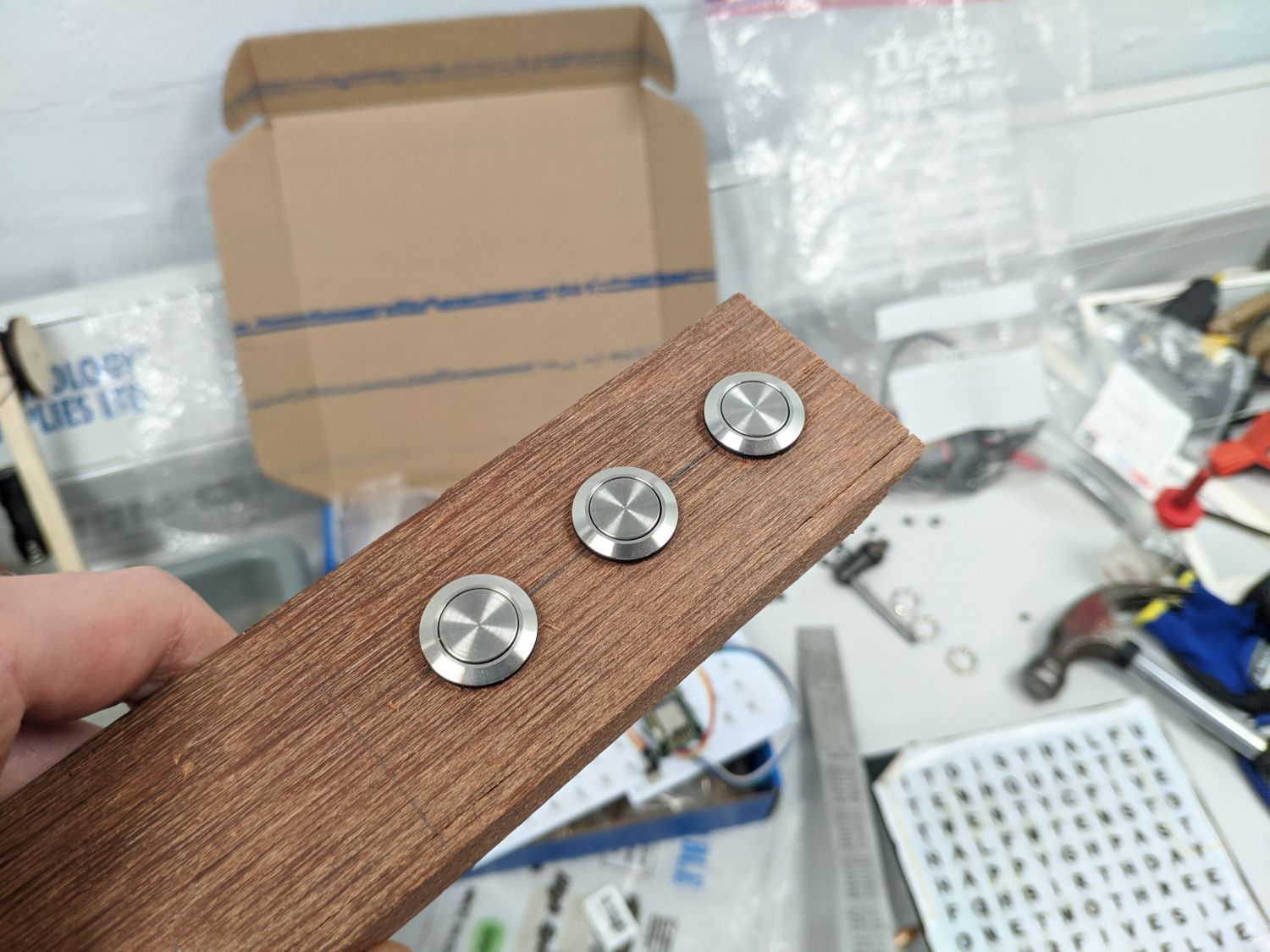
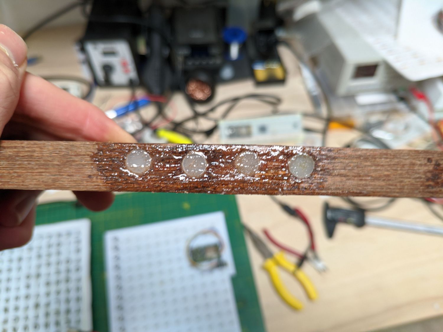
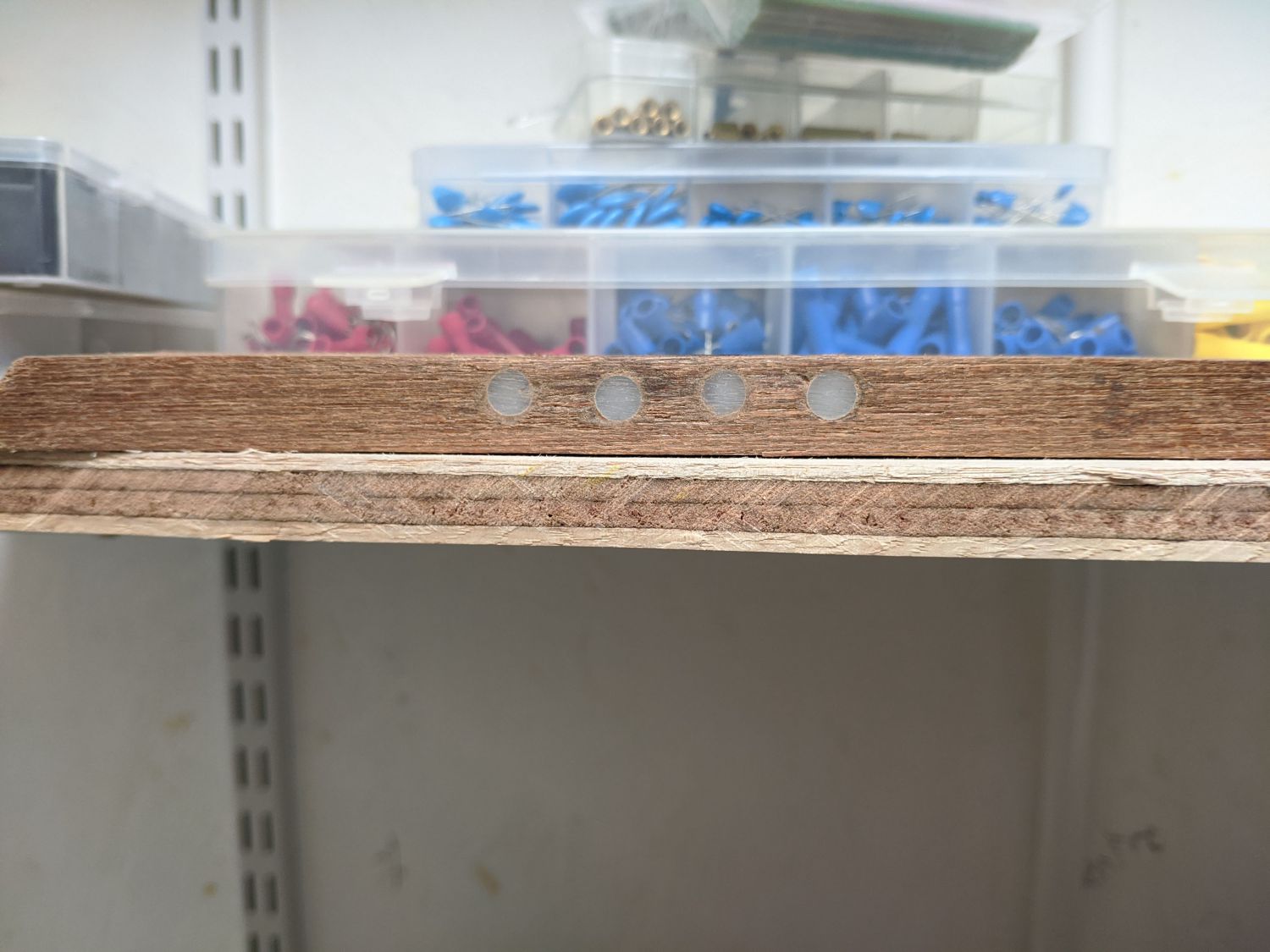
Next, I added some details to the border, this included cutting holes for the buttons and minute LEDs. I finished the minute LEDs by using epoxy to glue in opal diffusers, then sanding them back.
With the border modifications done, I dry fit it around the front plate then used a picture frame clamp to glue two of the four joints. These wont be particularly strong but shouldn’t ever be under much of a load.
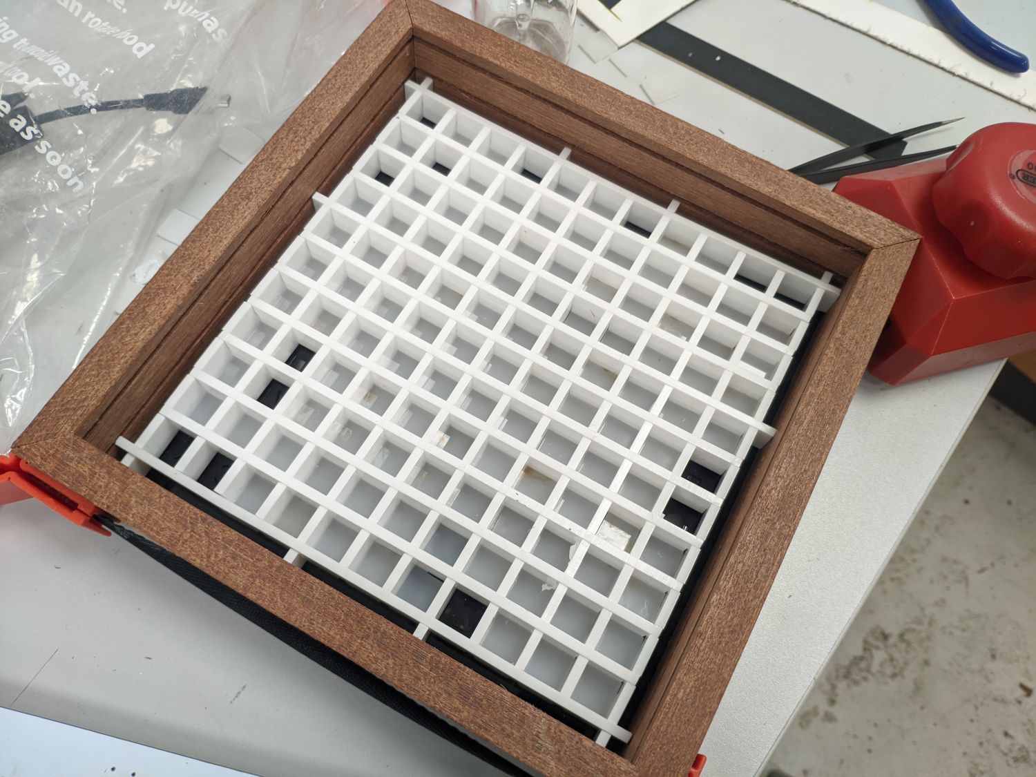
The acrylic grid sits up against the front plate and once in place, I pushed through the 121 opal diffusers to press against the back of the face. I then glued the letter islands back in place.
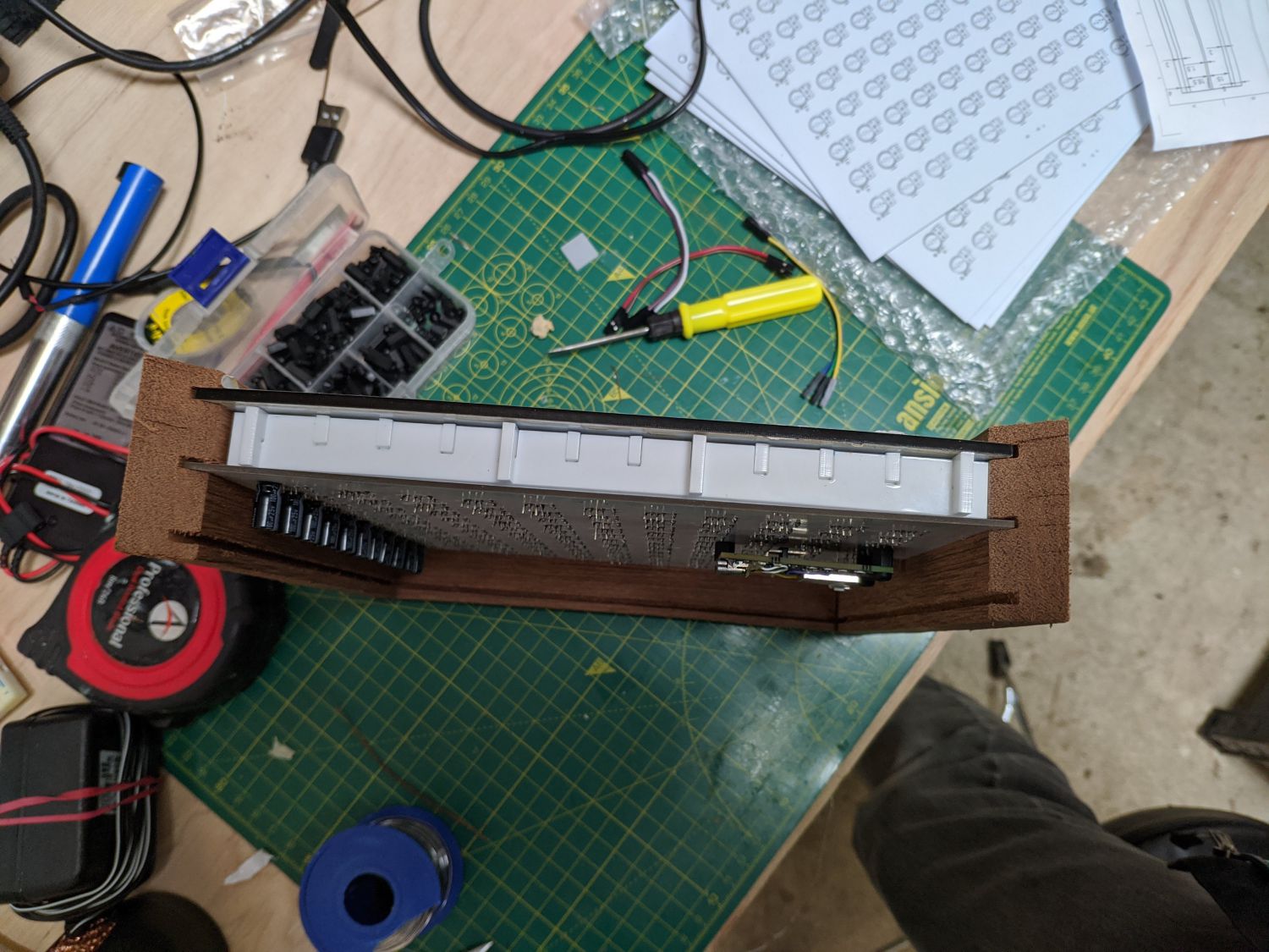
The final assembly step was to slot in the PCB and back plate before closing off the top!
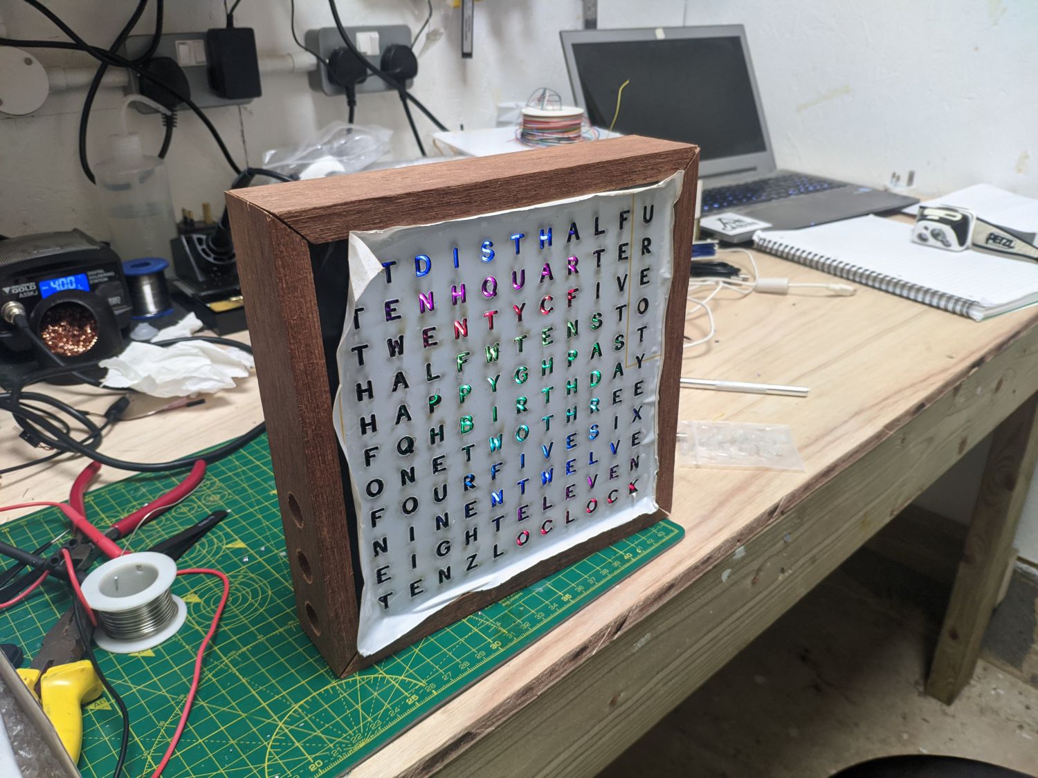
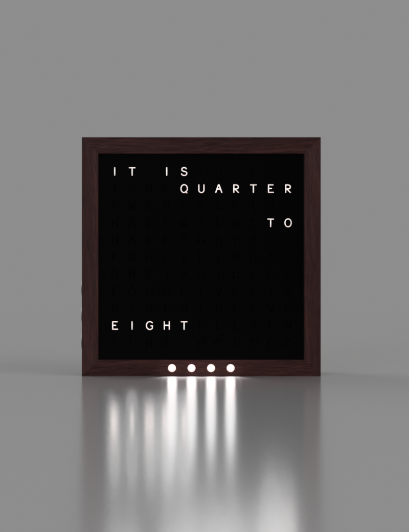
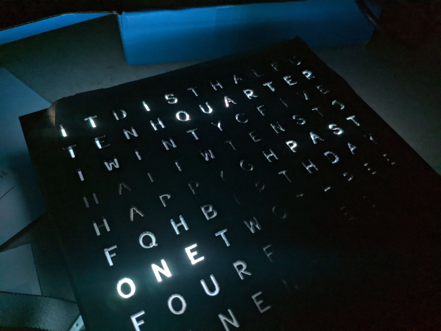
With that the first prototpe the Wordy clock was complete, but a significant problem soon became apparent. Due to flexing of the laser cut grid caused by the friction fit of each section, there was significant light bleed between letters. This is demonstrated in the video showing the clock cycling through all programmed times. Use of a 3D printed grid might work better to prevent light bleeding as it would sit flatter against the front plate and PCB.
Another problem I encountered was around fixing the top border timber. This cannot be glued as access may be required for maintenance, but steel right angle brackets were unable to pull the border to rigidity.
It was also at this stage that I noticed the lettering for ‘seven’ was missing and realised I would need to manufacture a further iteration to fix all of these issues.