A few years ago I began to work on a word clock project – a clock that instead of displaying the time by pointing or showing numbers, lights up the time in English. This means they look pretty fancy and are arguably easier to read than standard clocks.
In this series of posts I will document my process of designing and manufacturing a desktop word alarm clock I’ve named ‘Wordy’.
Working principles
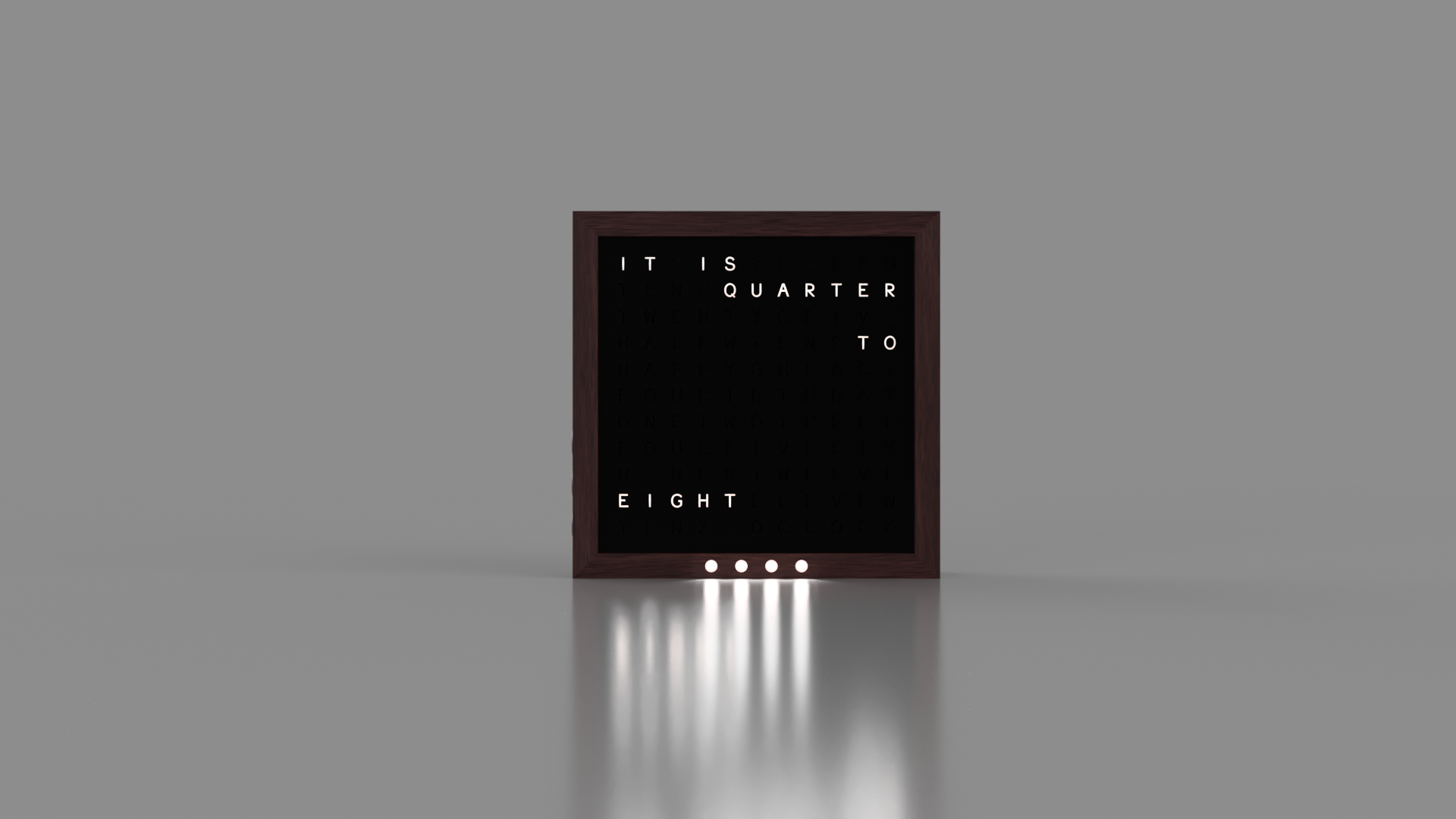
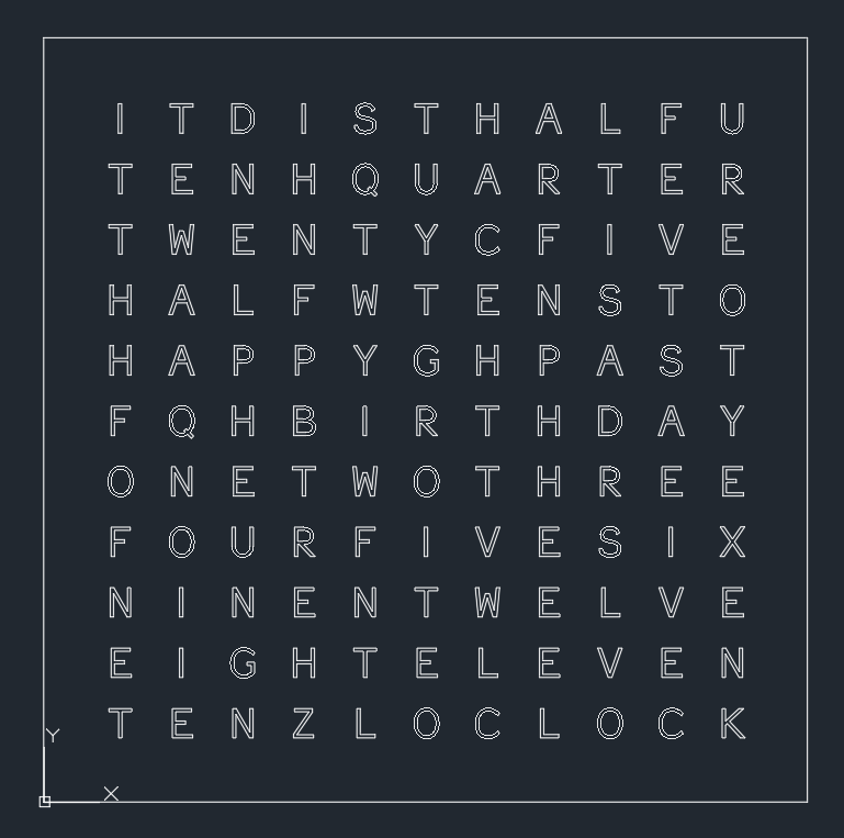
The main display of the clock is an LED matrix with each LED behind a single letter on the clock face. The face, arranged in a square of letters, contains every word required to describe the time in order to the nearest five minutes. The words are also in the right order so the time can be read off easily. The internal control board turns on and off individual words to ensure the correct time is always shown.
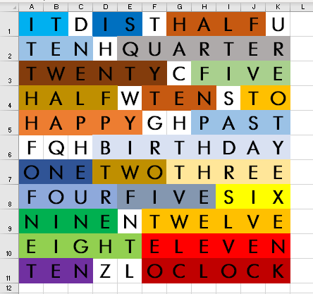
I began in Excel, arranging all the words I needed in an 11×11 grid. You may notice that “seven” is missing – I didn’t until I had already finished the first prototype so this is something I will need to fix in the future. Extra letters were just filled in randomly.
For more precision, I included an additional 4 LEDs at the base of the clock. These indicate time passed in minutes.
Electronics
The electrical design in this project was split into two main parts, the display wiring and the control board.
LED arrangement
I designed the display a few years ago and was trying to avoid complexity. This meant using THT (through hole) components and individually addressable LEDs.
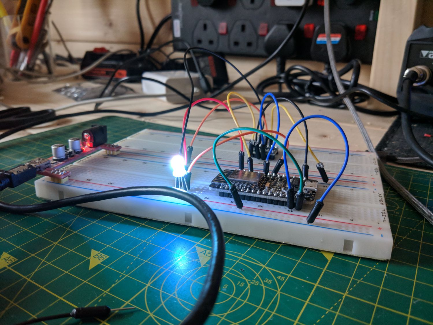
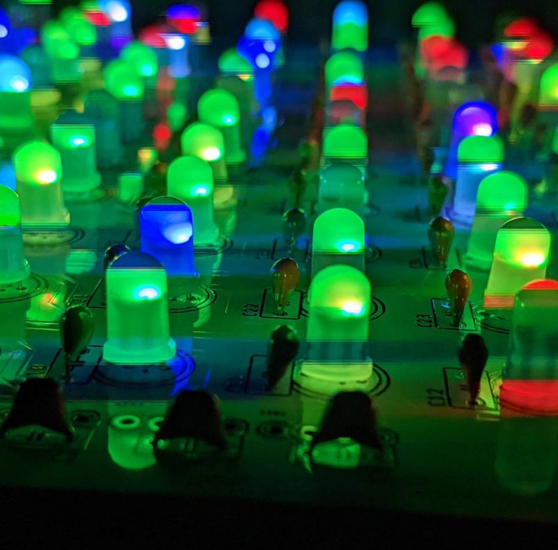
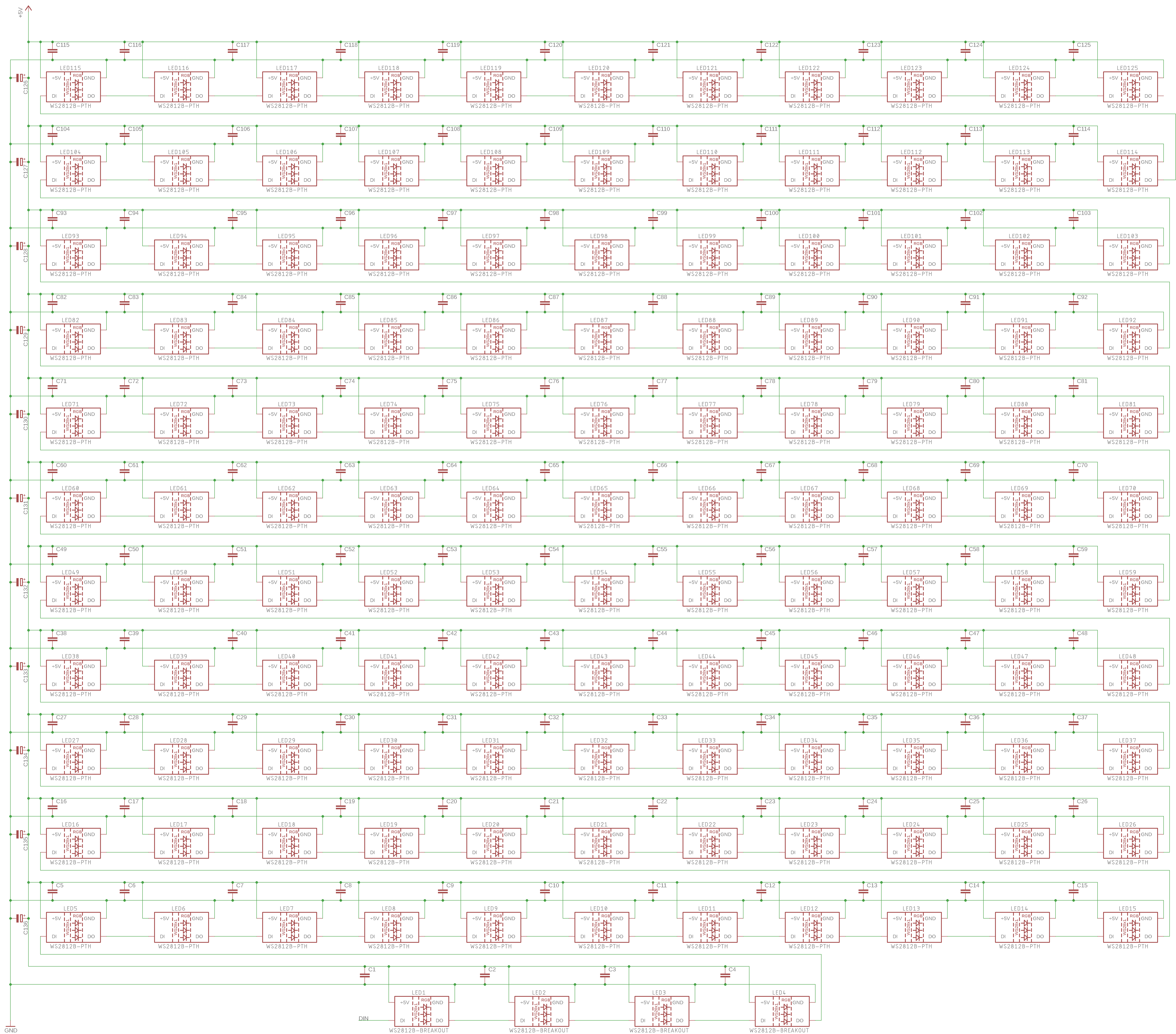
The LEDs I chose were standard 5mm WS2812Bs; these are RGB and run off 5V. Each package features a data in and a data out pin, allowing daisy chaining. The number of LEDs that can be driven from a single data pin is theoretically limitless (ignoring write speed) as each device contains an IC that not only reads the data signal, but also cleans it up for the next LED.
While I do refer to this setup as an “LED matrix”, it’s not actually wired as one as each LED-IC package just feeds into the next. The alternative to individually addressable LEDs would have been an actual diode matrix with each column and row requiring a data pin; unfeasible without complex multiplexing.
The main drawback of WS2812Bs is their power usage: each device can draw up to 60mA @ 5V. For 121 LEDs this meant a supply of ~8A was required. I decided this would be better left to an external power supply as didn’t want to make the case any bigger.
Display board
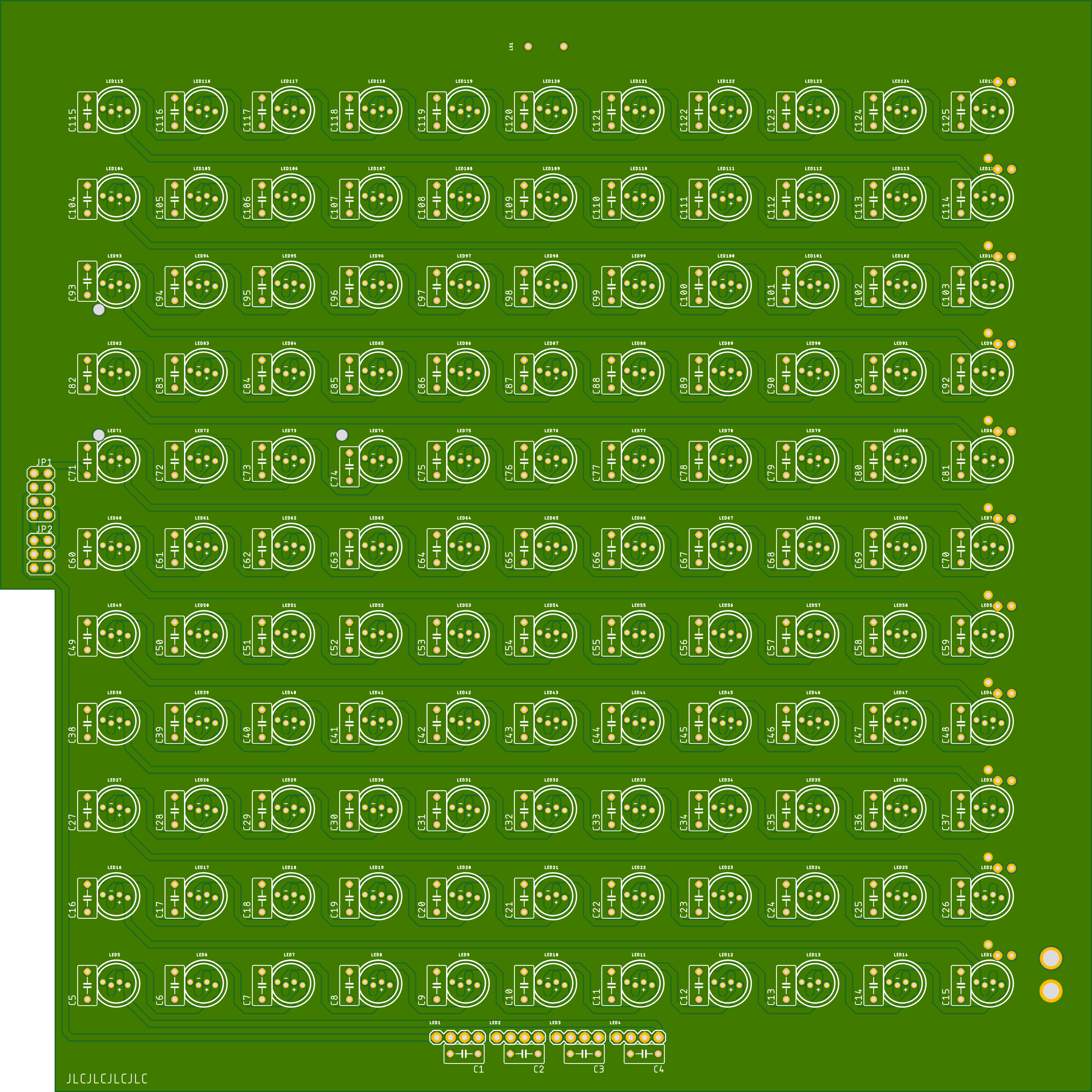
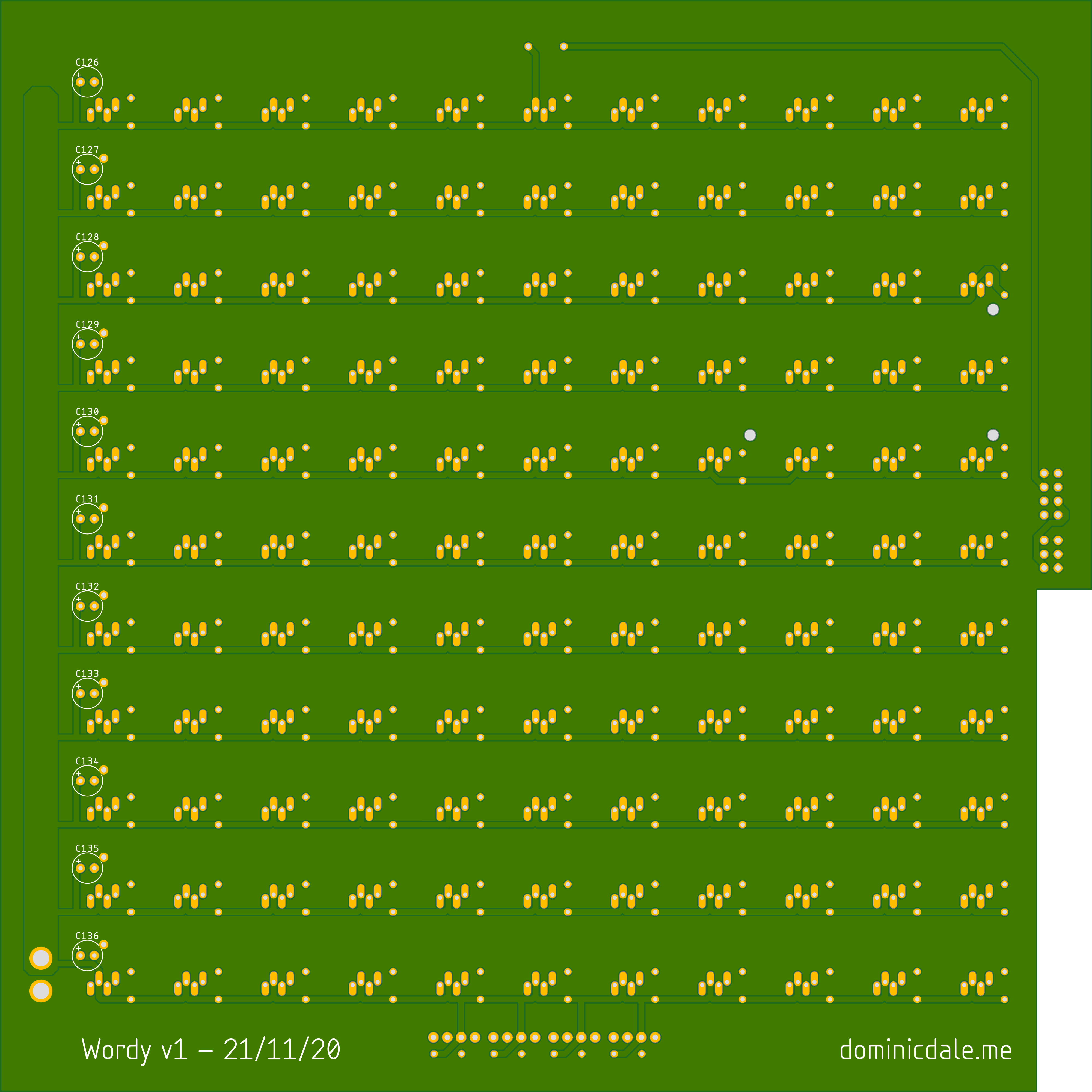
Because of the high currents involved I used thick traces (rated according to IPC-2221) to deliver power to each LED. The back of the board is used for power delivery and the front connects the data pins.
The main power ‘rail’ on the side of the board could carry up to 8A so it had to be >10mm wide on 1oz copper to keep the temperature rise low. I used a ground pour on both sides of the board to ensure all components could easily connect to ground.
Directly next to each LED is a 100nF capacitor to respond to immediate changes in current. Additionally, 11x 100uF capacitors accommodate larger changes in current.
Various I/O pins are present on the board for interfacing with the controller and buttons in the chassis. I added a cut-out to make sure the buttons would fit as intended. At the top of the board is a breakout for a piezoelectric buzzer for use as an alarm clock.
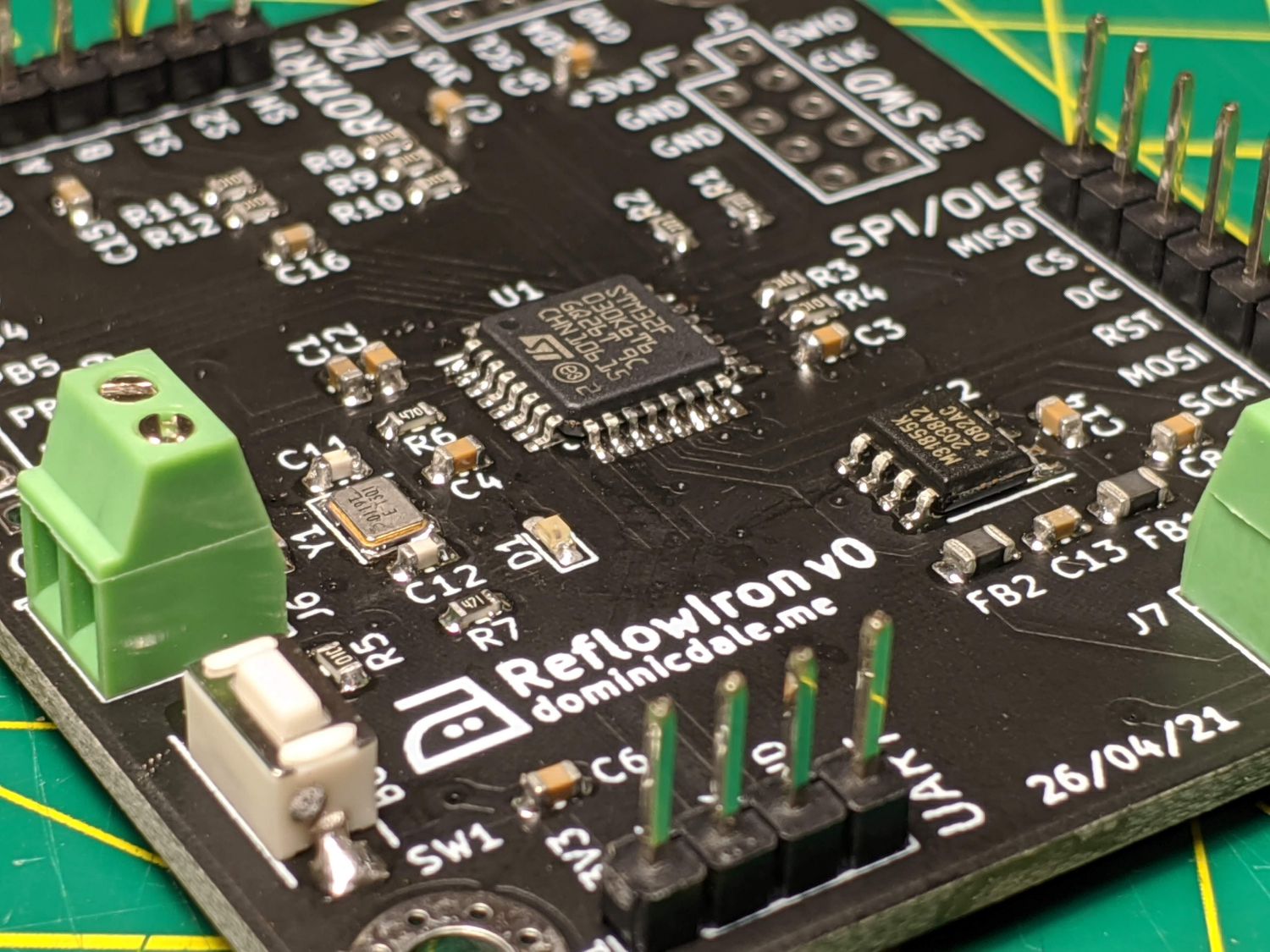
Control board
The control board contains circuitry to drive the LEDs and communicate with a computer. It is based around the ESP-12S microcontroller. I chose the ESP as it has WiFi built in which means the time can regularly be synced with a server.
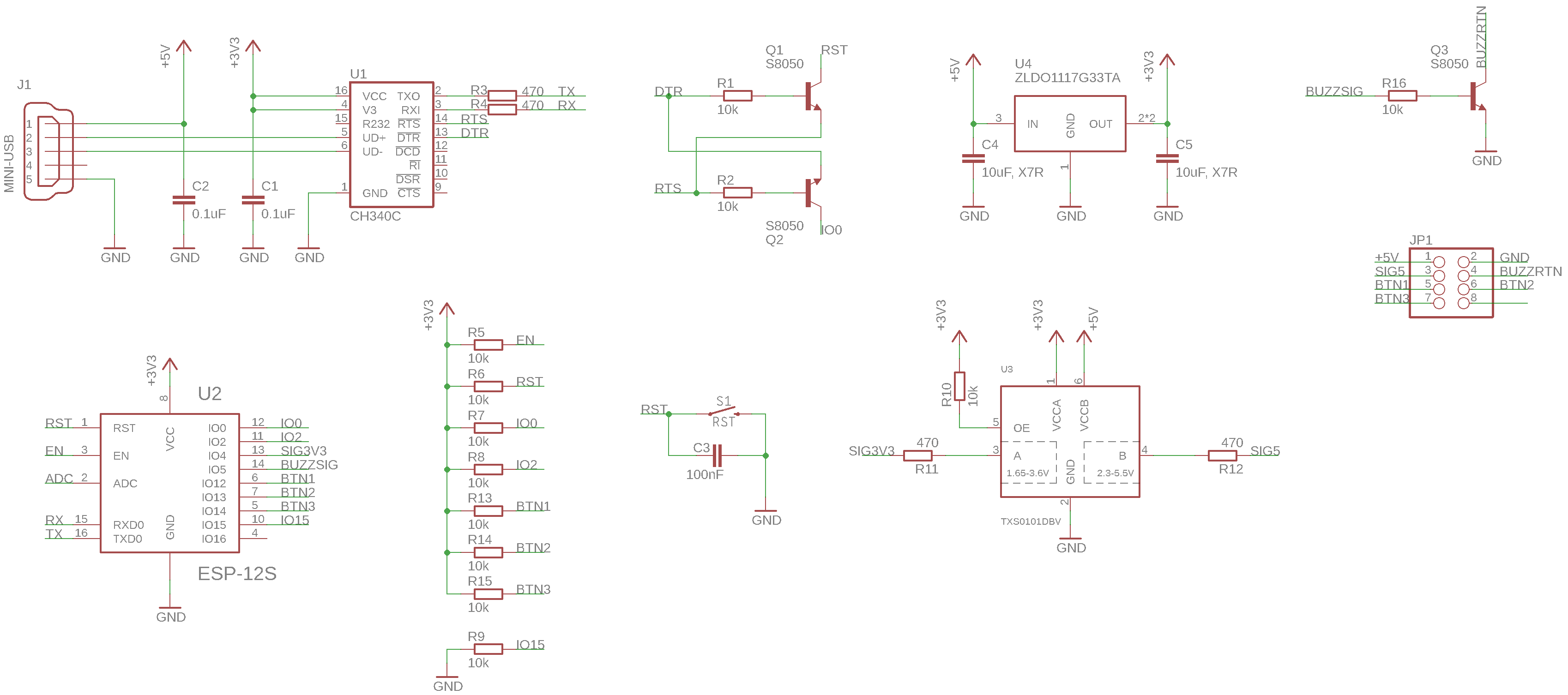
There are two key errors I made in the schematic, both to do with the CH340C (USB to serial chip). Firstly, the D+ and D- pins are connected the wrong way around. I also incorrectly wired TXO to the TX and RXI to the RX of the ESP-12S: these two connections should have been swapped.
The control board also contains:
- An LDO linear regulator so it can step down the 5V power supply to the 3.3V ESP-12S logic voltage.
- A TXS0101 level shifter to shift the 3.3V LED driving signal to 5V for the WS2812Bs.
- An NPN transistor to drive the buzzer.
- Various other components for ESP-12S operation.
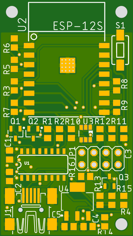
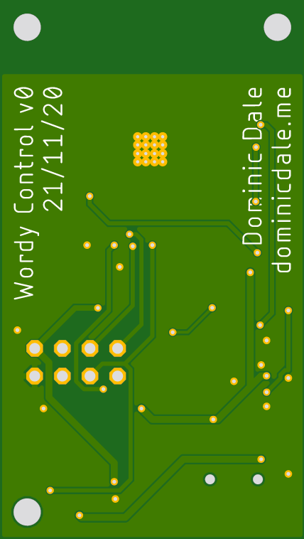
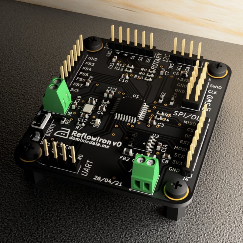
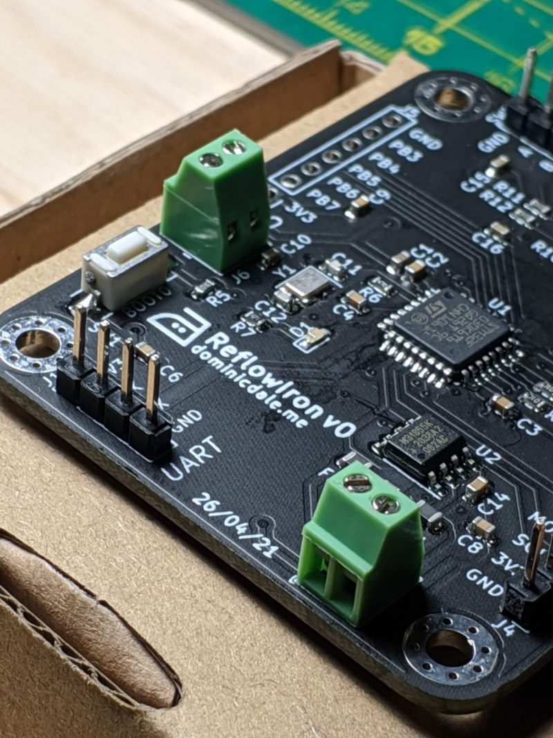
By the time I designed this board (late last year) I had begun to experiment with SMT technology and challenged myself to keep the control board as small as possible. All passives are 0805 (2*1.2mm) size and the only through hole component is the header.
Like the display board, both sides of this design feature ground fills except for the area below antenna; this is to prevent potential interference.
Mechanical construction
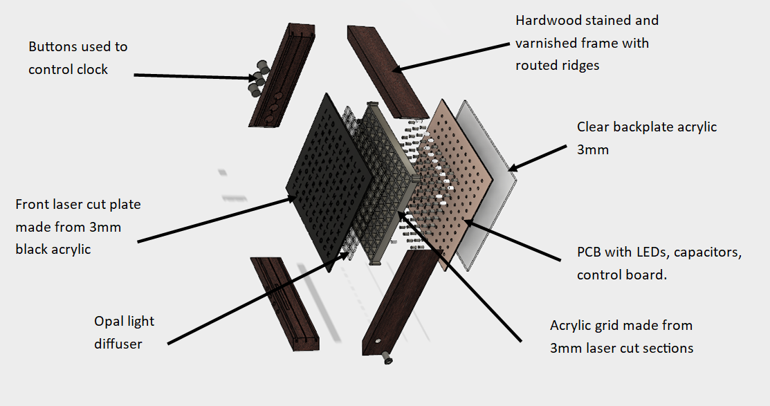
The entire clock construction is held together by a timber frame with slots cut to accommodate the front panel, PCB and back panel.
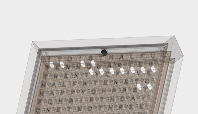
The front panel of the clock is cut from 3mm black acrylic and backs directly against a grid. This prevents light from neighbouring LEDs bleeding across letters and is constructed from acrylic slotted together. In each pixel of the grid an opal acrylic square is inserted to diffuse the LED light. The grid is held in place by the front panel and the PCB behind it. In each square of the grid an LED and capacitor poke through. The control board is mounted onto the display board with stand-offs and electrically connected with a ribbon cable. Finally, the back plate allows for easy viewing of the circuitry.
The timber frame keeps everything in place and has various holes including for control buttons and minute LEDs.
Software and app
I decided to develop the clock software before buying parts which included development of an android app.
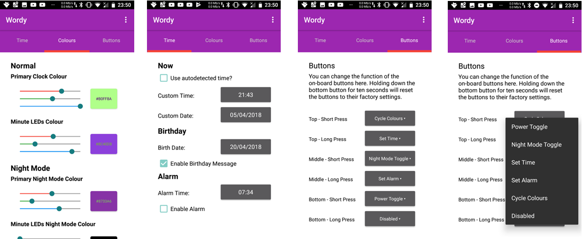
When plugged in, the ESP-12S board connects to the WiFi and hosts a server allowing communication from local devices. The code on the microcontroller interprets different HTTP GET requests based on their URL. This allows setting of all clock settings – including colours, times, button functions and alarms – while also letting devices fetch the current settings.
The app simply gets the existing settings on launch and then allows the posting of get requests to update settings as desired: all that is required is the IP of the microcontroller.
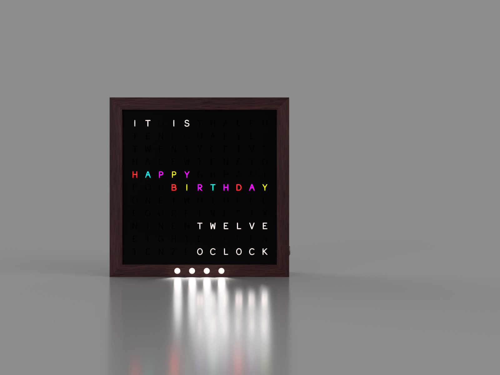
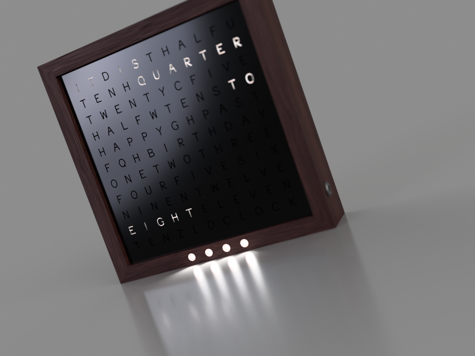
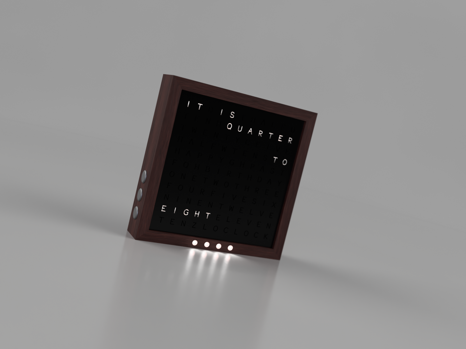
Gallery and conclusion
Below are some renders of Wordy v0 – in a future post I will build the first prototype!