The first stage of the project was lots of research and planning, followed by preparation of the site the building was to sit on. To make the final building fit my requirements I knew it needed to:
- be fully insulated and heated for year round use.
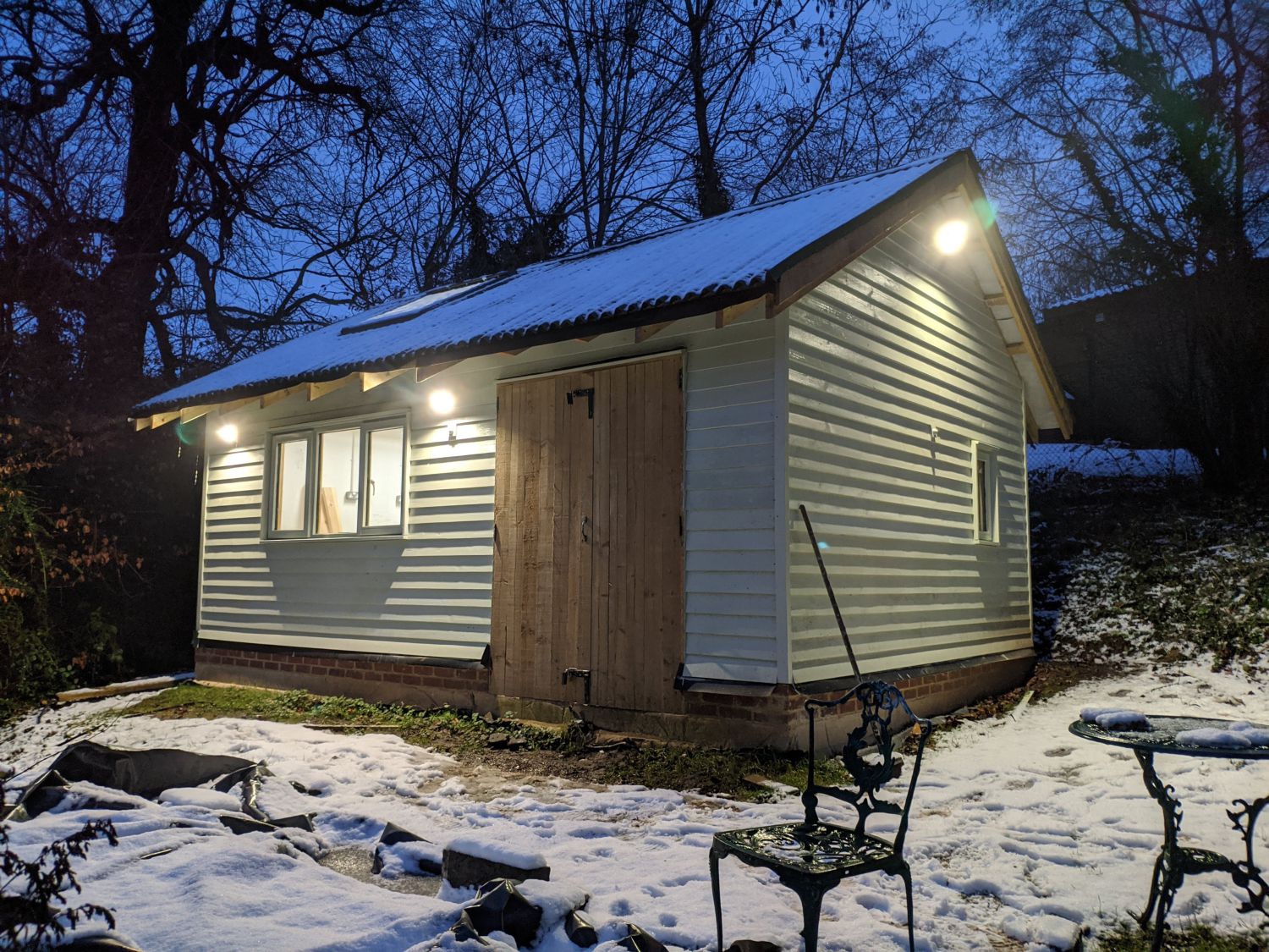
- have a pitched roof, mainly for aesthetics but also to provide storage space.
- be well lit and have large enough windows to provide natural light.
- be large enough to work in and fit any future equipment I may want to store in it.
- have two seperate areas (or rooms) to allow both dusty work (such as woodwork) and electronics work.
Planning
Initial floorplans
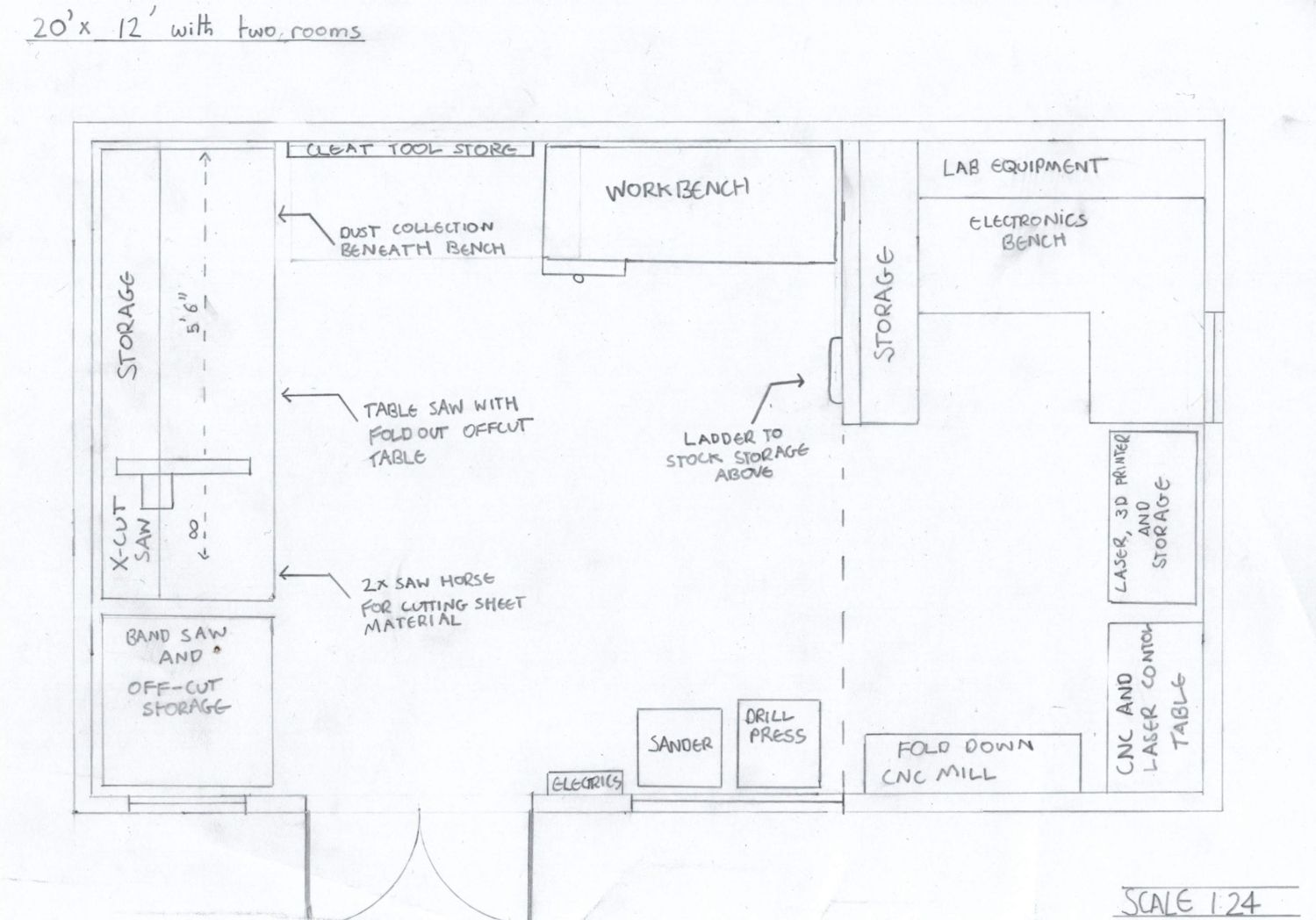
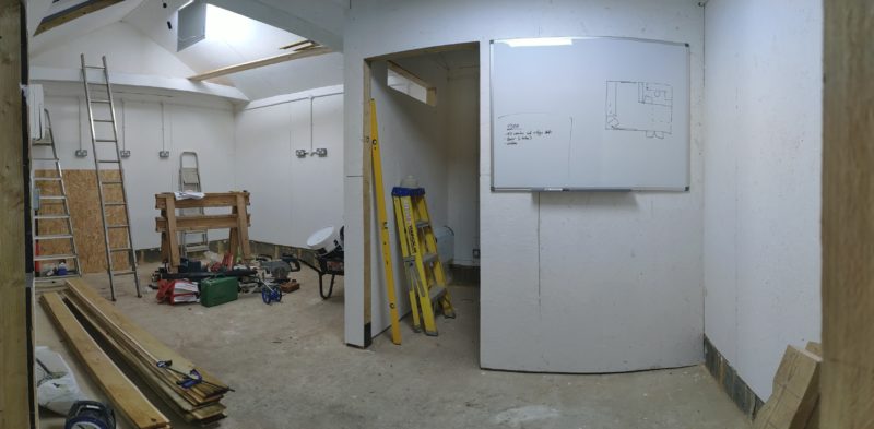
I began to experiment with floorplan layouts showing some of the things that I anticipated filling the space; I tried to make sure I left enough area to work in which meant fitting tools around the sides of the room and maximising potential use of walls. Initially I designated two seperate areas in the workshop for dusty and clean jobs but soon realised a seperate room was the best option for keeping dust off sensitive equipment. From the beginning I planned to have two windows, a large front facing one and a smaller one in the electronics area; this was to allow adequate light while still keeping the shed easy enough to secure with shutters.
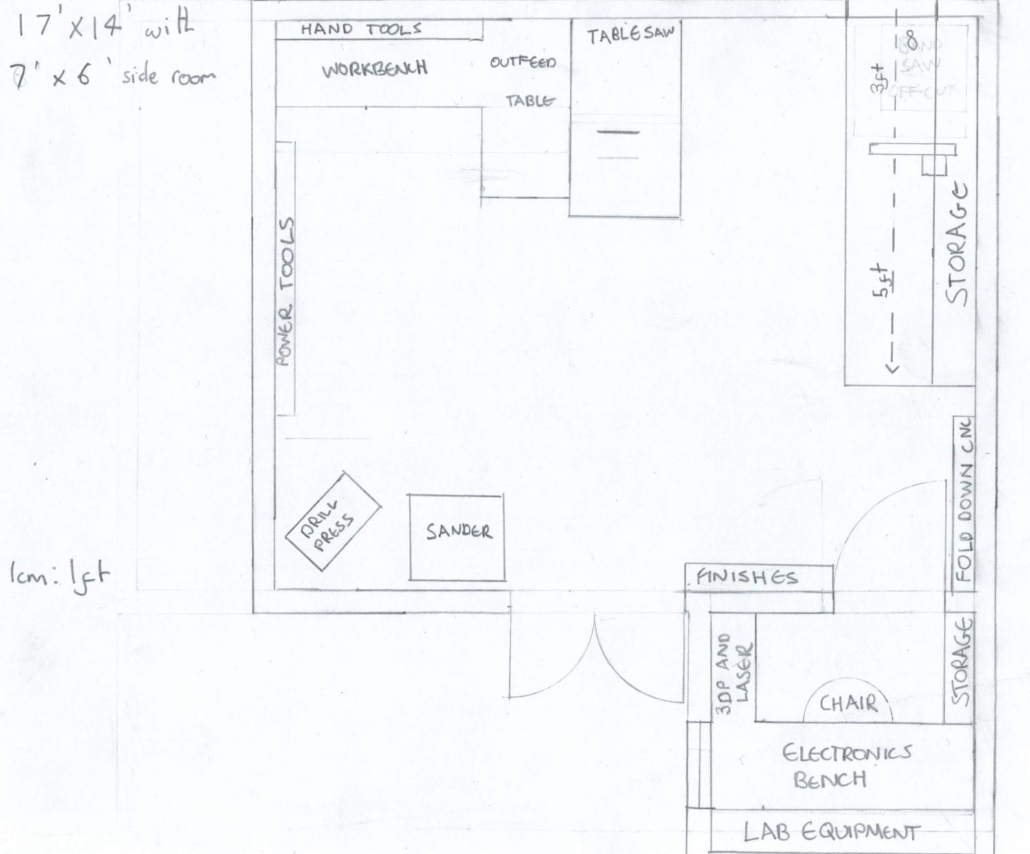
I also wanted to keep the building process straightforward so while I did experiment with L shaped layouts, I decided in the end to stick with a rectangular building avoiding a complex roof and extra walls. The advantage of such a layout is that usable floor space can be maximised as each inner room is rectangular in itself. The eventual floorplan I chose has a small entrance corridor before the main room.
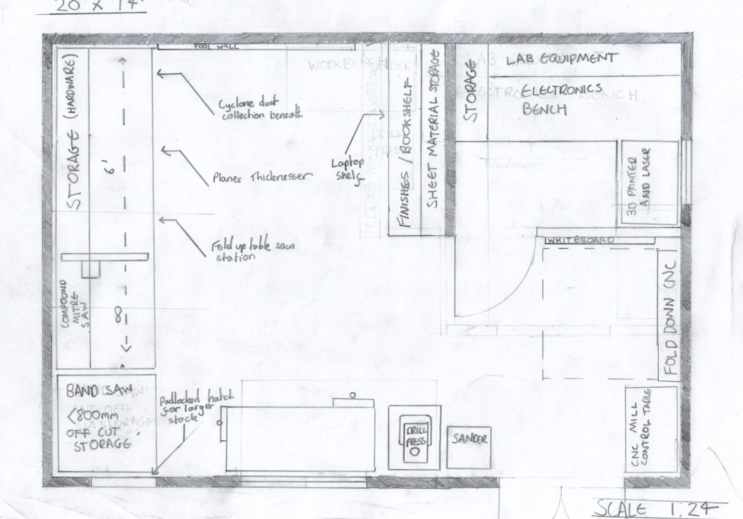
I decided to place my entrance to the right side of the shed so the large window would align with a gap in the trees down the hill. All walls are taken advantage of in this design with shelves, an area to use a computer, a cleat wall for power tools and backing for multiple benches.
The design
The building’s design is heavily based off a design by Mike G on UKWorkshop which can be found here. Key features include:
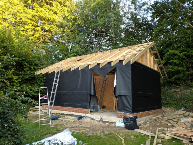
- A raised brick plinth to keep the timber frame off the ground, critical to the longevity of the building. I ended up using three courses of bricks and a 50mm block so the featheredge lines up nicely with the dwarf wall.
- The use of OSB as a vapour barrier to prevent condensation within the building, this OSB ‘sheathing’ is on the inside of the insulation for this reason unlike how timber framed buildings are often constructed. The OSB is also structural.
- A ventilated cavity behind the cladding to allow moisture evaporation; this cavity also means rain that has penetrated through the cladding can run down the inside of the wall and escape the building.
Site preparation
Flattening and digging
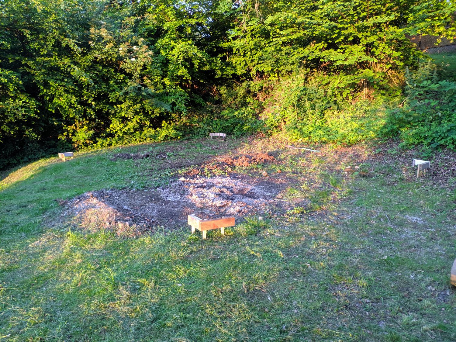
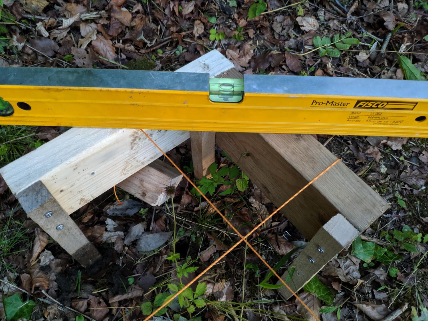
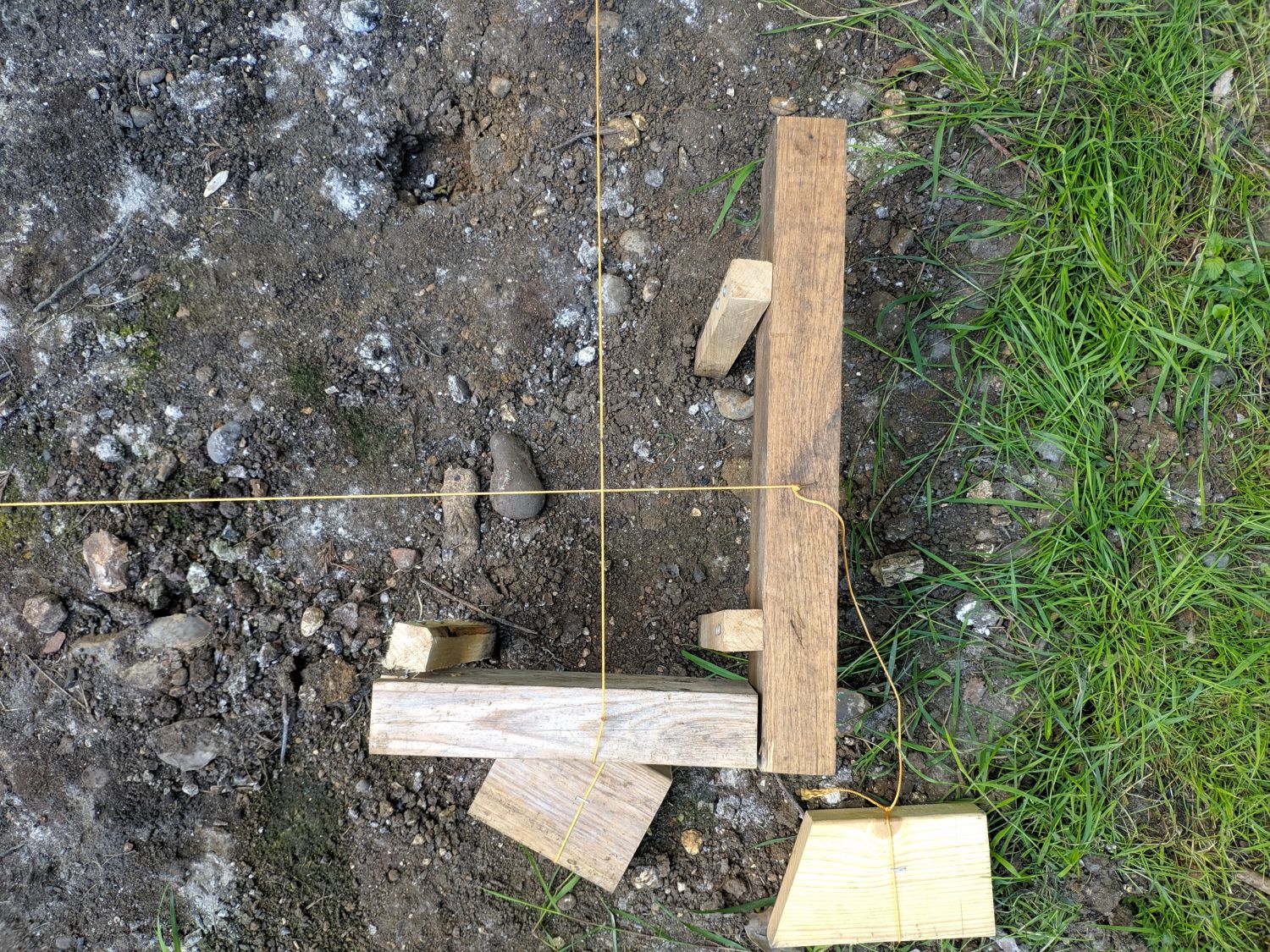
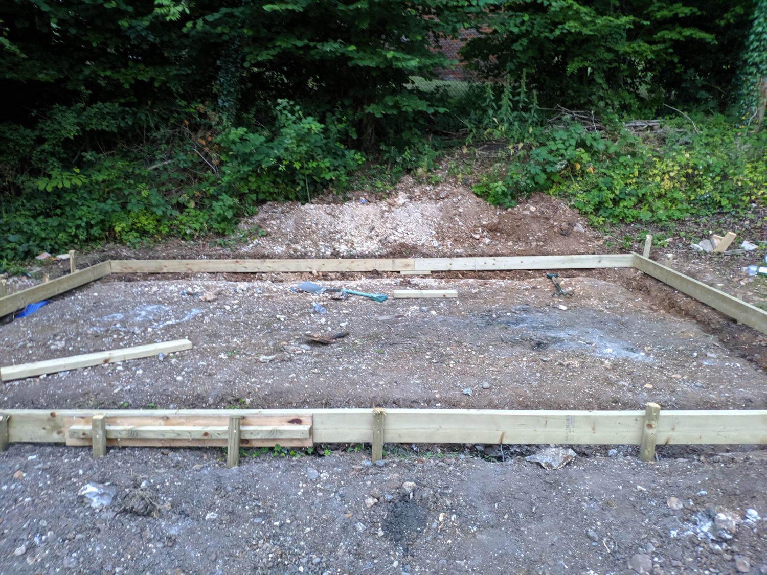
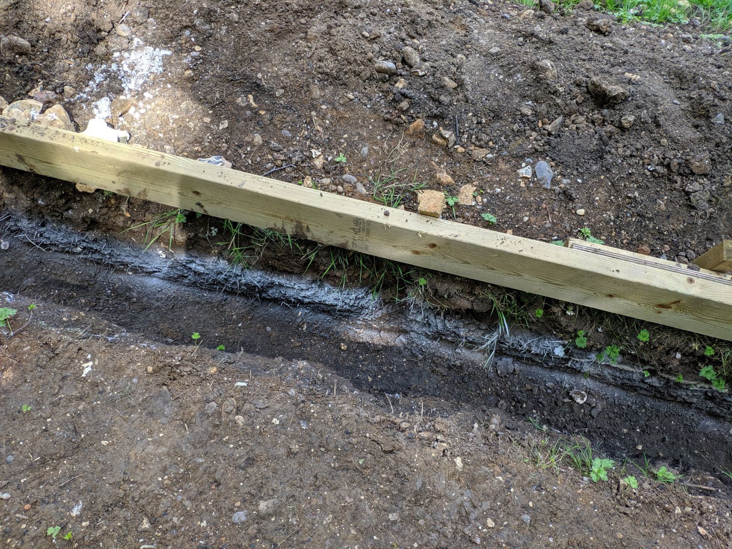
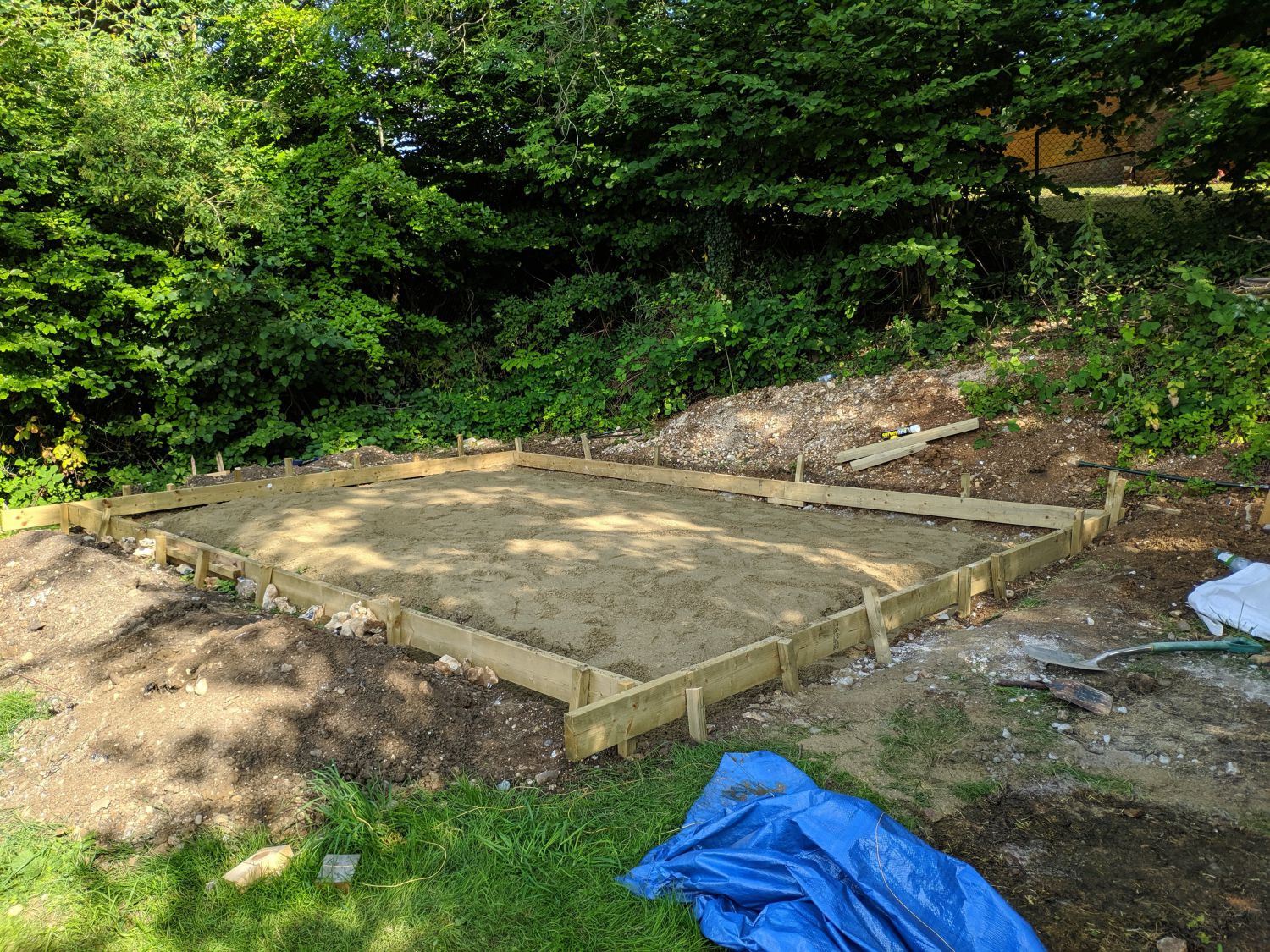
Once I had a basic idea of how the building would go together, I needed to flatten out an area big enough to fit the foundation. First I set up batter boards and squared a 20ft*14ft area, the size of my foundation (as this was still on a slight slope this wouldn’t have been perfect). I then, with help, used a mattock and spade to transfer earth from the hill side of the foundation to the lower side. The final result was a fairly flat site ready for trenches to be dug. Trenches 1ft in width were then dug down to the subsoil, more compacted soil with a different composition and hence lighter colour than the topsoil.
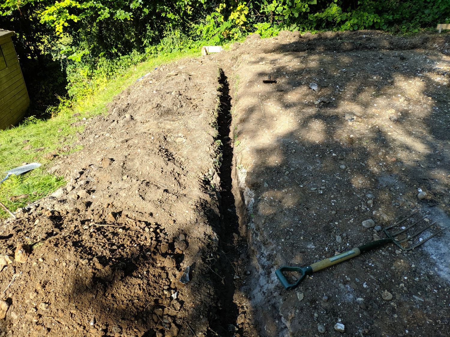
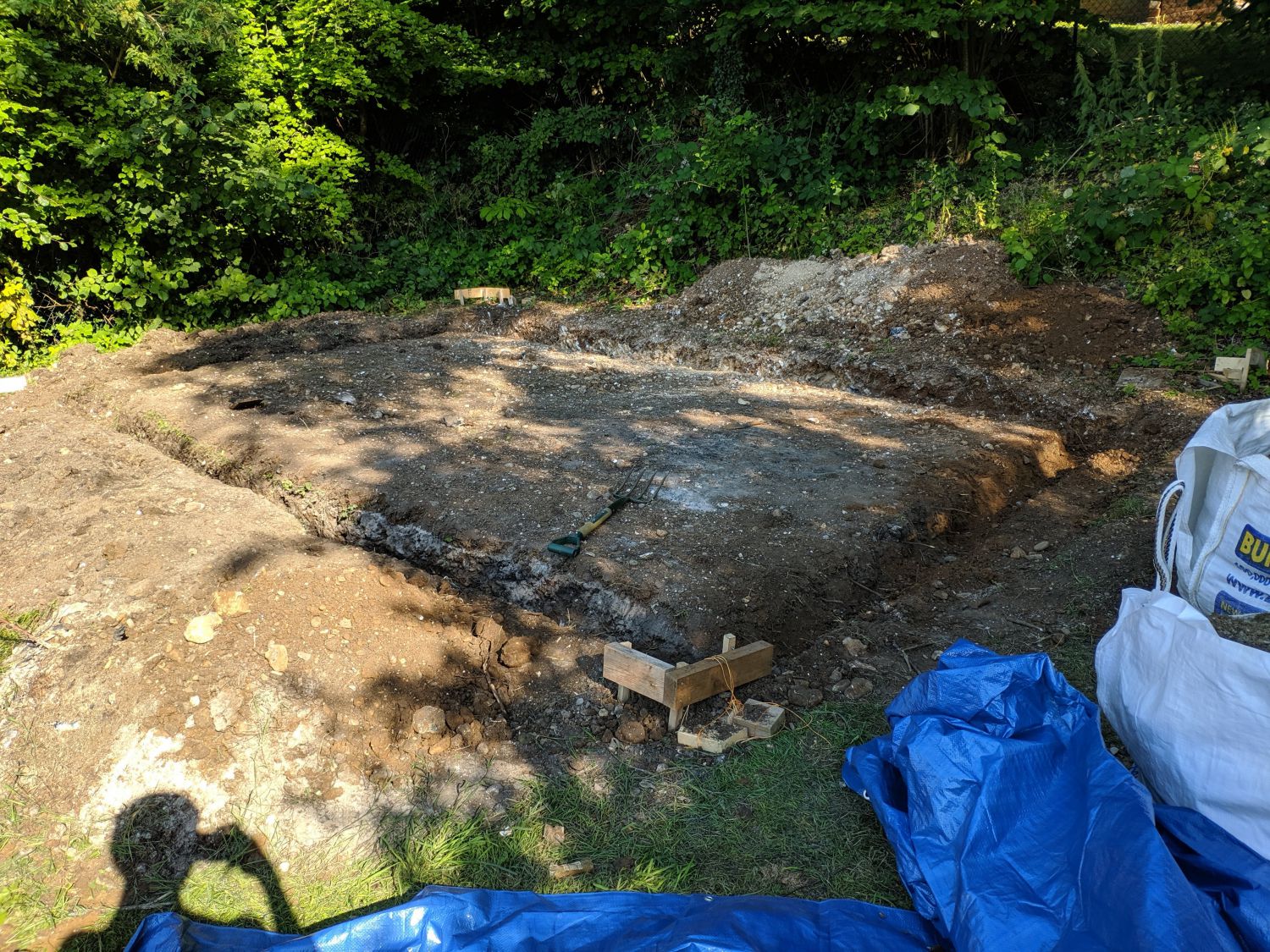
The site was now ready for formwork to be constructed.
Concrete forms
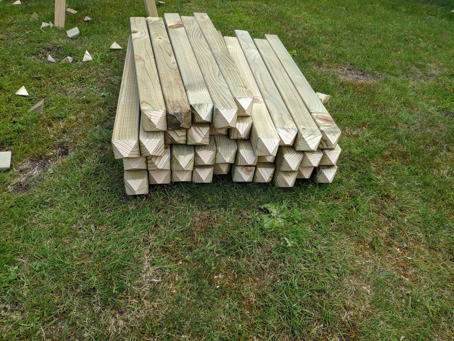
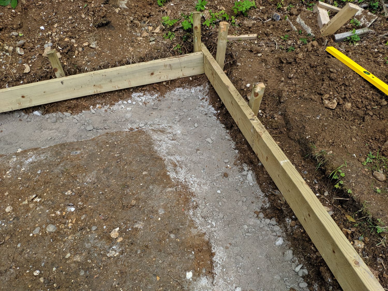
My forms were to be constructed from 6×2 timbers, staked into the ground at ~2ft O.C. by 2×2 stakes. To save money I cut the stakes myself, but as the angle I could achieve on my mitre saw was limited, I had to use a sledgehammer to properly sink the stakes. I first created a single corner, confirming it was 90° using a 3′,4′,5′ triangle then sunk a post at the opposite end. I had to use reinforced plywood cleats on two of the boards to create enough length for the entire building.
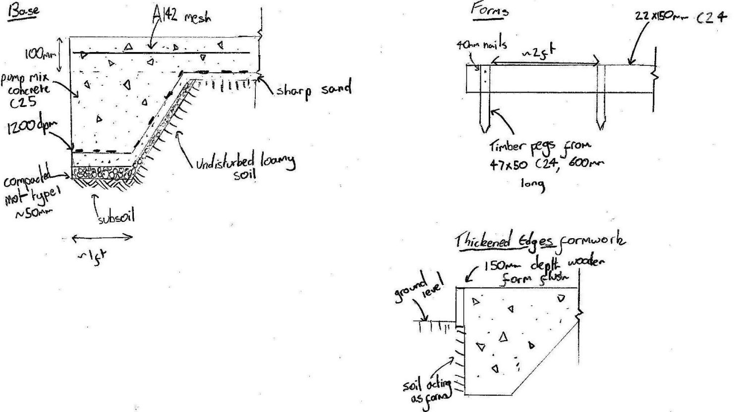
Sub-base, sand blinding and DPM
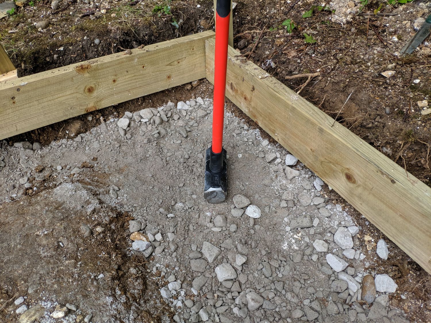
The next job was to create a sub-base of MOT type 1 for the dpm and concrete to sit on. After moving a bulk bag of the sub-base with a wheelbarrow to the hilltop site, I filled each of the trenches evenly. I then used to top of my sledgehammer as a hand tamper, ensuring all of the MOT 1 was fully seated.
I then covered the area, both the trenches and topsoil centre, with a 50mm layer of sand (I used sharp sand) to prevent stones in the sub-base piercing the DPM.
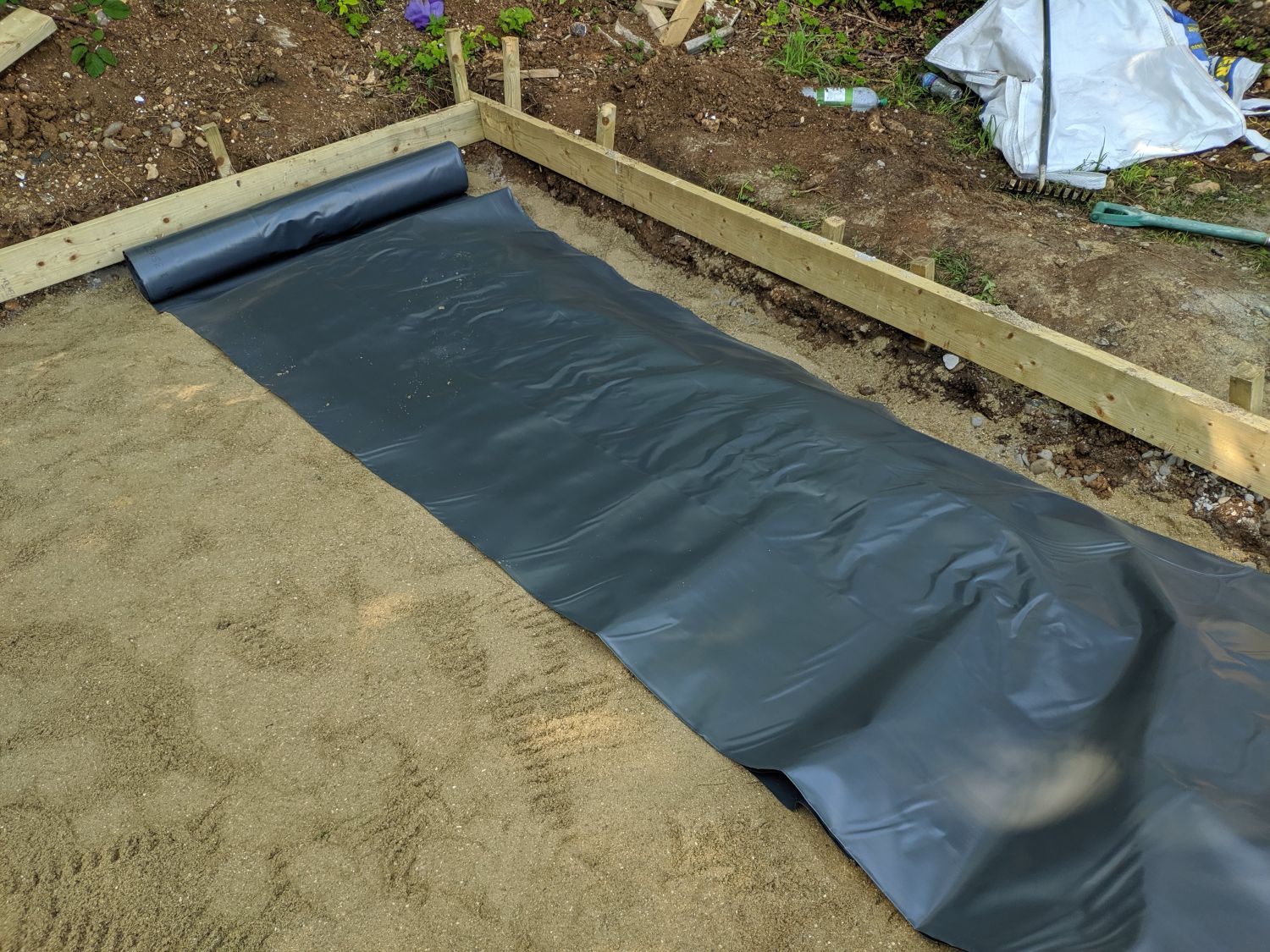
Once the sand had been raked evenly I rolled out the DPM (1200 gauge). This was lapped and sealed with appropriate tape. Initially I had planned to cut the DPM short at the bottom of the trench; this is advisable for this sort of slab as when water gets into it, the DPM rising at the corner can catch and contain it. I did however wrap the membrane up as there were gaps in my form between the top of the trenches and bottom of the timbers, the DPM filled this gap.
Reinforcement
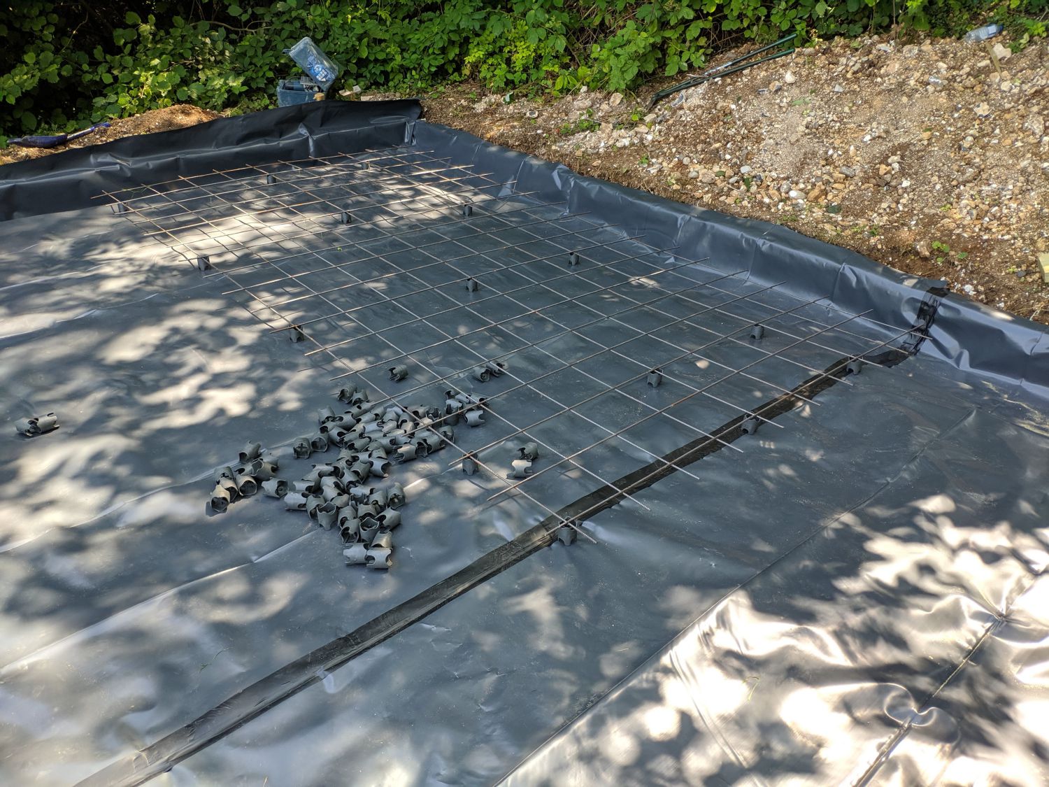
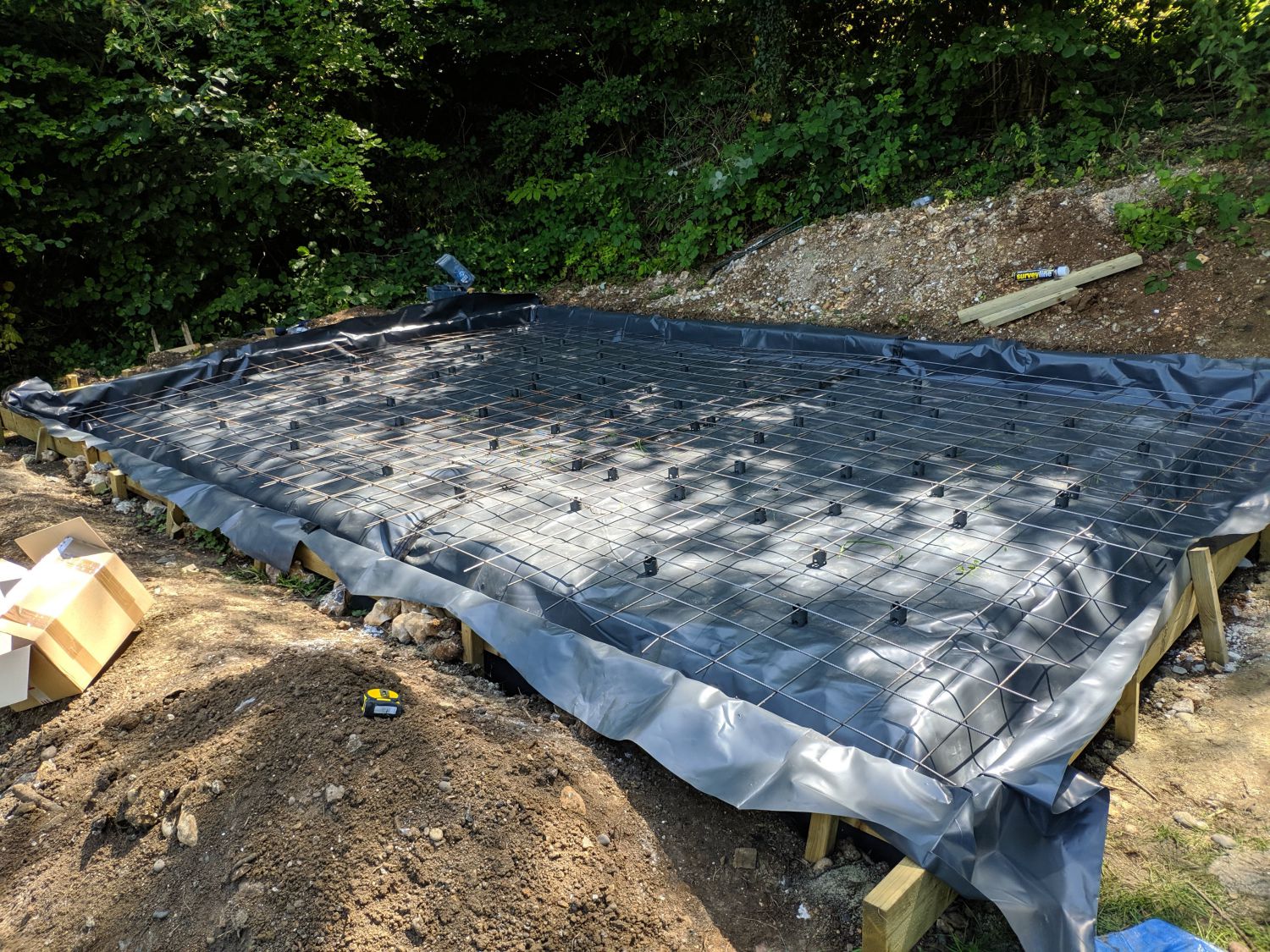
Finally, I needed to add the steel mesh reinforcement to the slab. I used 4 A142 mesh ‘sheets’ and connected them with steel wire. All edges were 50mm from the sides and the mesh was raised 50mm by plastic spacers (not recommended but concrete ones were out of stock).
Conclusion
One thing I forgot to add until the evening before the pour was the conduits for cables to run through the slab; I simply taped these to the exterior DPM and secured them to the mesh with steel wire.
The site was now ready for concrete and the plinth!